OpenGL Tessellation
Overview
Tessellation is subdividing concave polygons or polygons with intersecting edges into convex polygons. Since OpenGL accepts only convex polygons for rendering, these non-convex polygons must be tessellated before rendering.
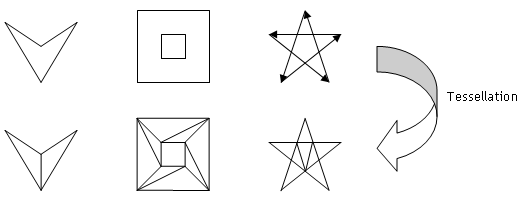
Download: tessellation.zip, stencilTess.zip
The basic procedure of tessellation is sending all vertex coordinates of a non-convex polygon to the tessellator instead of sending them directly to OpenGL rendering pipeline, and then tessellating the polygon by the tessellator. Finally, once tessellation is done, tessellator calls actual OpenGL commands to render the tessellated polygon through the user-defined callback routines.
OpenGL provides a collection of routines to process concave polygons to convex polygons:
GLUtessellator* gluNewTess()

void gluDeleteTess(GLUtessellator *tess)
gluNewTess() creates a tessellator object and gluDeleteTess() deletes the tessellator object. If failed to create one, it returns NULL pointer.
void gluTessBeginPolygon(GLUtessellator *tess, void *userData)

void gluTessEndPolygon(GLUtessellator *tess)
Instead of using glBegin() and glEnd() block to describe all vertices of a polygon, you need to use tessellator-specific block, gluTessBeginPolygon() and gluTessEndPolygon(). You must describe non-convex polygon between this block.
void gluTessBeginContour(GLUtessellator *tess)

void gluTessEndContour(GLUtessellator *tess)
A polygon may have more than one closed contour(closed loop), for example, a polyon with a hole in it has 2 contours, inner and outer contours. Each contour must be wrapped within this block, gluTessBeginContour() and gluTessEndContour(). It is the nested block inside gluTessBeginPolygon() and gluTessEndPolygon() block.
void gluTessVertex(GLUtessellator *tess, GLdouble cords[3], void *vertexData)
gluTessVertex() specifies a vertex of a contour. Tessellator uses these vertex coordinates to perform tessellation. All the vertices should approximately lie on the same plane. The second parameter is the vertex coordinates required for tessellation, and the third parameter is the data used for actual rendering. It may be not only vertex coordinates but also color, normal and texture coordinates.
void gluTessCallback(GLUtessellator *tess, GLUenum type, void (*fn)())
During tessellation process, tessellator will call a series of callback routines when it is ready to render the tessellated polygon. You must provide appropriate callback functions, which contain actual OpenGL commands to render the polygon, such as glBegin(), glEnd(), glVertex*(), etc.
The following snippet code is an example of general usage.
// create tessellator
GLUtesselator *tess = gluNewTess();

// register callback functions
gluTessCallback(tess, GLU_TESS_BEGIN,   beginCB);
gluTessCallback(tess, GLU_TESS_END,     endCB);
gluTessCallback(tess, GLU_TESS_VERTEX,  vertexCB);
gluTessCallback(tess, GLU_TESS_COMBINE, combineCB);
gluTessCallback(tess, GLU_TESS_ERROR,   errorCB);

// describe non-convex polygon
gluTessBeginPolygon(tess, user_data);
    // first contour
    gluTessBeginContour(tess);
        gluTessVertex(tess, coords[0], vertex_data);
        ...
    gluTessEndContour(tess);

    // second contour
    gluTessBeginContour(tess);
        gluTessVertex(tess, coords[5], vertex_data);
        ...
    gluTessEndContour(tess);
    ...
gluTessEndPolygon(tess);

// delete tessellator after processing
gluDeleteTess(tess);
Examples
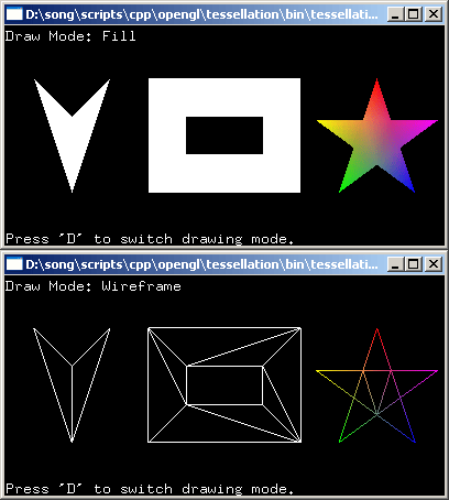
There are 3 tessellation examples: the left is a simple concave polygon with 4 vertices, the middle one has a hole in it, and the right is a self-intersecting polygon (a star shape).
Download the source and binary: tessellation.zip
A simple concave polygon
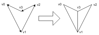
The tessellation routine of this contour is described in tessellate1(). OpenGL tessellator decides the most efficient primitive type while performing tessellation; GL_TRIANGLE, GL_TRIANGLE_FAN, GL_TRIANGLE_STRIP and GL_LINE_LOOP. For this case, tessellator triangulates it with GL_TRIANGLE_FAN.
You can record actual OpenGL commands in the callback functions, which are performed during tessellation. The following codes are generated by tessellator and recorded in callback functions. See the each callback function in the source file how it was recorded.
glBegin(GL_TRIANGLE_FAN);
    glVertex3dv(v3);
    glVertex3dv(v0);
    glVertex3dv(v1);
    glVertex3dv(v2);
glEnd();
Notice that the winding of this polygon is counter-clockwise (CCW), which tells the surface normal of this polygon is coming out of the plane. If the winding is clockwise (CW), the normal vector is opposite direction, so you are looking at the back face instead of the front. You can explicitly define the surface normal by using gluTessNormal().
void gluTessNormal(GLUtessellator *tess, GLdouble x, GLdouble y, GLdouble z)
If you specify the normal vector with (0,0,1), then you will always see the front face even if the winding of contour is CW (I assume the camera is looking at default direction, -Z). The default normal value is (0,0,0), which means tessellator will compute the normal from the given vertices and winding.
A polygon with hole

The second example has 2 counter-clockwise (CCW) inner and outer contours (loops) and is defined in tessellate2(). Tessellator generates actual OpenGL commands as the following: 1 triangle strip and 1 triangle.
glBegin(GL_TRIANGLE_STRIP);
    glVertex3dv(v1);
    glVertex3dv(v5);
    glVertex3dv(v0);
    glVertex3dv(v4);
    glVertex3dv(v3);
    glVertex3dv(v7);
    glVertex3dv(v2);
    glVertex3dv(v6);
    glVertex3dv(v5);
glEnd();
glBegin(GL_TRIANGLES);
    glVertex3dv(v5);
 glVertex3dv(v1);
    glVertex3dv(v2);
glEnd();
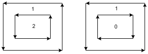
You may wonder how OpenGL tessellator knows the middle area is a hole (not filled). The answer is the winding rules and winding numbers. Tessellator assigns winding numbers to the regions partitioned by multiple contours. For this case, there are 2 separate regions: the winding number of the inner region is 2 and the outer area is 1. Given default winding rule, GLU_TESS_WINDING_ODD, the areas marked with odd numbers will be filled and the even number areas won't be filled.
If the inner contour is clockwise revolution, the winding number of the inner area is now 0 and the outer area is still 1. Therefore, the inner region remains still as a hole (not filled) because the winding number of inner area is not odd, which is 0. The winding rules are explained in the next section.
A self-intersecting polygon
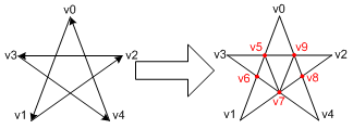
The last example is a star shape, self-intersecting polygon and is defined in tessellator3(). Notice that tessellator adds 5 more vertices where 2 edge lines are intersected, v5, v6, v7, v8, and v9. When the tessellation algorithm detects an intersection, then GLU_TESS_COMBINE callback function must be provided in order to create the new vertex data, so we can draw it later.
void combineCB(GLdouble newVert[3], GLdouble *neighbourVert[4],
               GLfloat neighborWeight[4], void **outData);
The combine callback function is used to create a new vertex data when 2 edge lines intersect. It takes four arguments: newVert[3] is an array of x, y, z coordinates as GLdouble. It is the position of the new intersected vertex which is found by tessellator. The second argument is an array of pointers of four existing neighbor vertices, which make the intersection of 2 edges. The third is an array of four weight factors of four existing neighbor vertices. The weights are used to compute interpolation values of color, normal, or texture coordinates at the intersecting point. The last argument is the pointer to the output vertex data. The output data may contain not only vertex coordinates but also color, normal and texture coordinates. Tessellator will pass the output data into your GLU_TESS_VERTEX callback routine in order to draw the intersecting vertex.
The following OpenGL commands are generated by tessellator; 2 triangle fans and 1 triangle.
glBegin(GL_TRIANGLE_FAN);
    glVertex3dv(v9);
    glVertex3dv(v0);
    glVertex3dv(v5);
    glVertex3dv(v7);
    glVertex3dv(v8);
    glVertex3dv(v2);
glEnd();
glBegin(GL_TRIANGLE_FAN);
    glVertex3dv(v6);
    glVertex3dv(v1);
    glVertex3dv(v7);
    glVertex3dv(v5);
    glVertex3dv(v3);
glEnd();
glBegin(GL_TRIANGLES);
    glVertex3dv(v4);
    glVertex3dv(v8);
    glVertex3dv(v7);
glEnd();
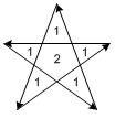
Consider the winding rules and winding numbers for this polygon. The polygon is divided into 6 separate regions, and the winding numbers are assigned as the figure.
With GLU_TESS_WINDING_ODD rule, the center region cannot be filled because the winding number is even. We need a different winding rule, so we can fill both odd and even numbered areas. For this case, the winding rule should be GLU_TESS_WINDING_NONZERO, which allows to fill all non-zero numbered regions. (GLU_TESS_WINDING_POSITIVE also works.)
Tessellator provides gluTessProperty() to change the winding rule and other properties, such as GLU_TESS_BOUNDARY_ONLY and GLU_TESS_TOLERANCE. See the next section for more details about winding rules.
void gluTessProperty(GLUtesselator *tess, GLenum property, GLdouble *value)

// Examples
gluTessProperty(tess, GLU_TESS_BOUNDARY_ONLY, GL_TRUE);
gluTessProperty(tess, GLU_TESS_WINDING_RULE, GLU_TESS_WINDING_NONZERO);
Winding Rules and Winding Numbers
Imagine that multiple contours, which are overlapped or nested each other, divide the plane into multiple regions. The winding rule determines which of these regions are inside or outside. So, the interior is filled and the exterior is not filled.
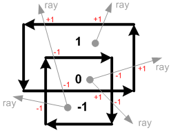
For each enclosed region which partitioned by multiple contours, OpenGL tessellator assigns a winding number to the region. Draw a ray from a point inside a region to infinity in any direction. Strating from 0, increase the winding number by 1 each time if the lay crosses a counter-clockwise contour path (from right to left), and decrease by 1 if the lay crosses a clockwise contour path (from left to right). After counting all the crossings, the winding number represents the region.
If the winding rule is GLU_TESS_WINDING_ODD, the regions with odd number are interior and are filled, and the even numbered regions are exterior and are not filled. Therefore, the region 1 and -1 will be filled and the region 0 will be a hole.
The possible winding rules are;
GLU_TESS_WINDING_ODD: Fill odd numbers, default setting
GLU_TESS_WINDING_NONZERO: Fill non-zero numbers
GLU_TESS_WINDING_POSITIVE: Fill positive numbers
GLU_TESS_WINDING_NEGATIVE: Fill negative numbers
GLU_TESS_WINDING_ABS_GEQ_TWO: Fill ABSolute values Greater than EQual to TWO
The following image shows the different interior regions (shaded) based on different winding rules. If GLU_TESS_WINDING_ABS_GEQ_TWO is set, nothing will be drawn (every regions are exterior).
