OpenGL Projection Matrix
Related Topics: OpenGL Transformation, OpenGL Matrix
- Overview
- Perspective Projection
- Infinite Perspective Matrix
- Perspective Matrix with Field Of View
- Orthographic Projection
Updates: The MathML version is available here.
Overview
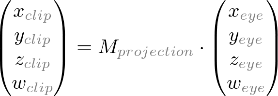
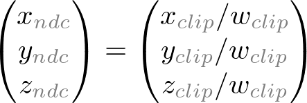
A computer monitor is a 2D surface. A 3D scene rendered by OpenGL must be projected onto the computer screen as a 2D image. GL_PROJECTION matrix is used for this projection transformation. First, it transforms all vertex data from the eye coordinates to the clip coordinates. Then, these clip coordinates are also transformed to the normalized device coordinates (NDC) by dividing with w component of the clip coordinates.
Therefore, we have to keep in mind that both clipping (frustum culling) and NDC transformations are integrated into GL_PROJECTION matrix. The following sections describe how to build the projection matrix from 6 parameters; left, right, bottom, top, near and far boundary values.
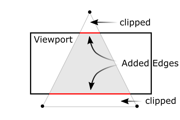
Note that the frustum culling (clipping) is performed in the clip coordinates, just before dividing by wc. The clip coordinates, xc, yc and zc are tested by comparing with wc. If any clip coordinate is less than -wc, or greater than wc, then the vertex will be discarded.
![]()
Then, OpenGL will reconstruct the edges of the polygon where clipping occurs.
Perspective Projection
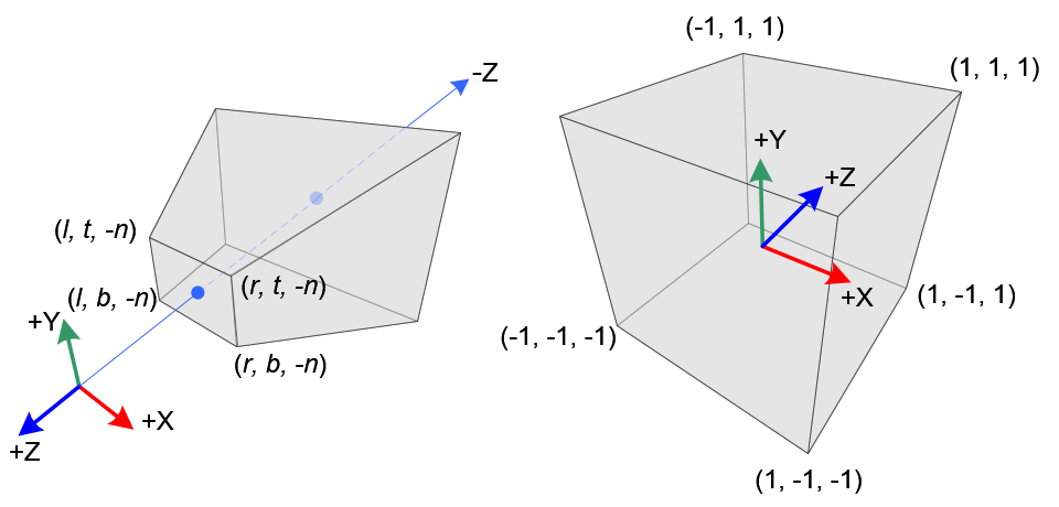
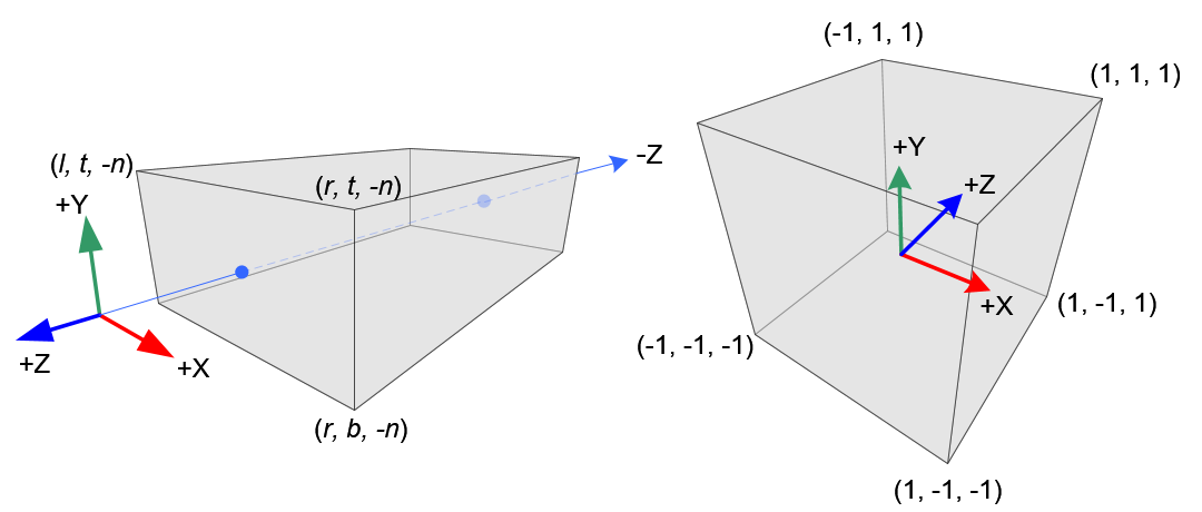
In perspective projection, a 3D point in a truncated pyramid frustum (eye coordinates) is mapped to a cube (NDC); the range of x-coordinate from [l, r] to [-1, 1], the y-coordinate from [b, t] to [-1, 1] and the z-coordinate from [-n, -f] to [-1, 1].
Note that the eye coordinates are defined in the right-handed coordinate system, but NDC uses the left-handed coordinate system. That is, the camera at the origin is looking along -Z axis in eye space, but it is looking along +Z axis in NDC. Since glFrustum() accepts only positive values of near and far distances, we need to negate them during the construction of GL_PROJECTION matrix.
In OpenGL, a 3D point in eye space is projected onto the near plane (projection plane). The following diagrams show how a point (xe, ye, ze) in eye space is projected to (xp, yp, zp) on the near plane.
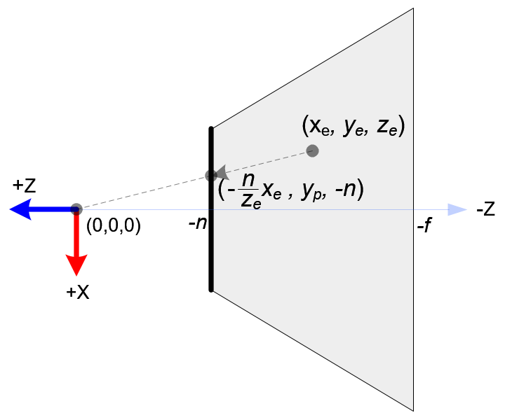
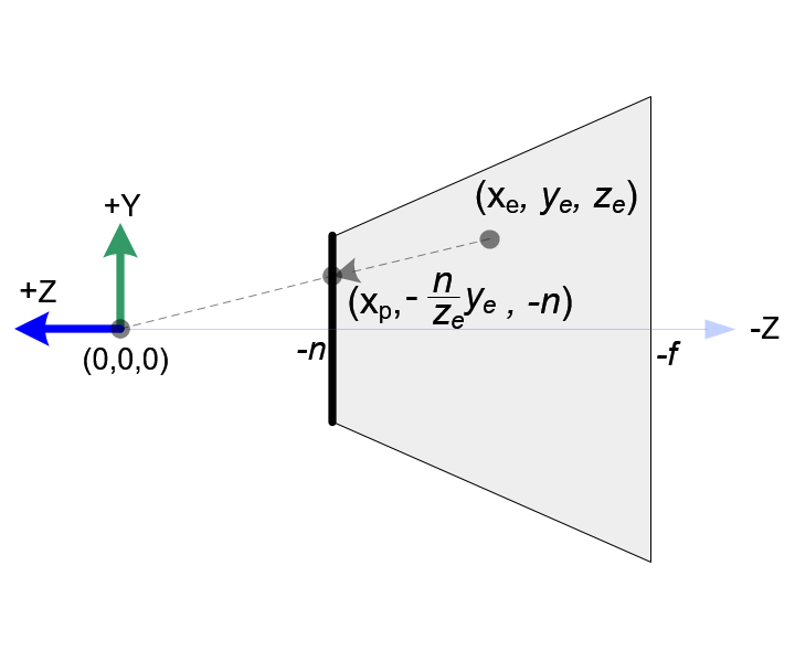
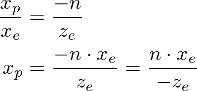
From the top view of the frustum, the x-coordinate of eye space, xe is mapped to xp, which is calculated by using the ratio of similar triangles;
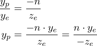
From the side view of the frustum, yp is also calculated in a similar way;
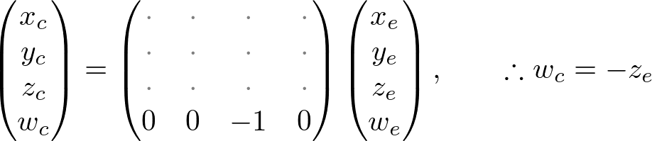
Note that both xp and yp depend on ze; they are inversely propotional to -ze. In other words, they are both divided by -ze. It is a very first clue to construct GL_PROJECTION matrix. After the eye coordinates are transformed by multiplying GL_PROJECTION matrix, the clip coordinates are still a homogeneous coordinates. It finally becomes the normalized device coordinates (NDC) by divided by the w-component of the clip coordinates. (See more details on OpenGL Transformation.)
 ,
,
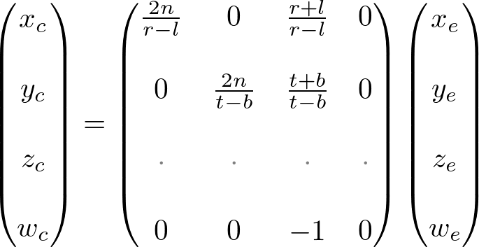
Therefore, we can set the w-component of the clip coordinates as -ze. And, the 4th of GL_PROJECTION matrix becomes (0, 0, -1, 0).
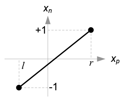
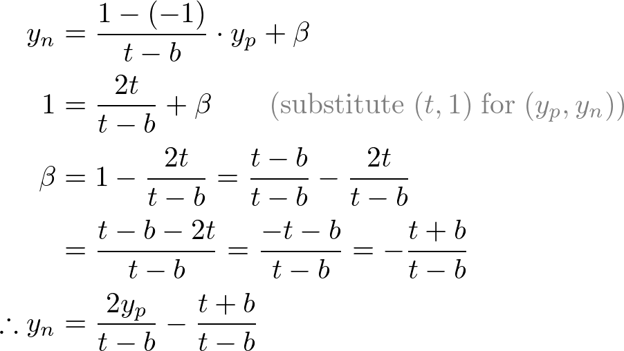
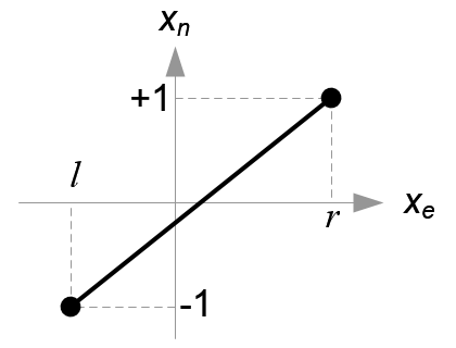
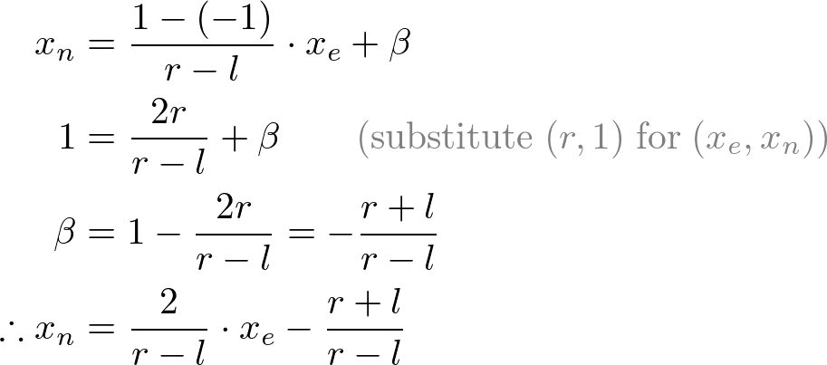
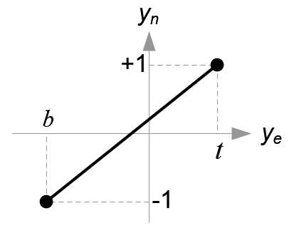
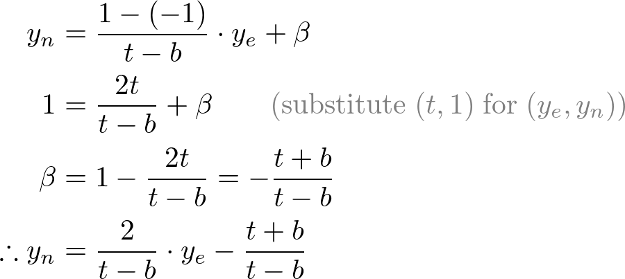
Next, we map xp and yp to xn and yn of NDC with linear relationship; [l, r] ⇒ [-1, 1] and [b, t] ⇒ [-1, 1].
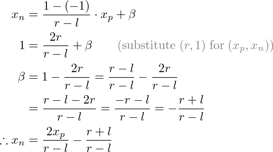
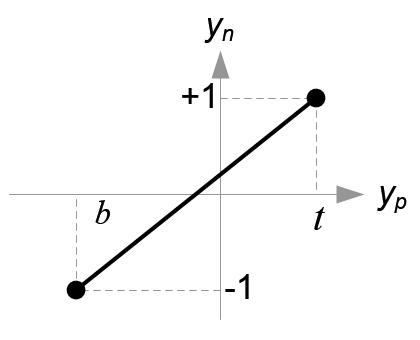
Then, we substitute xp and yp into the above equations.
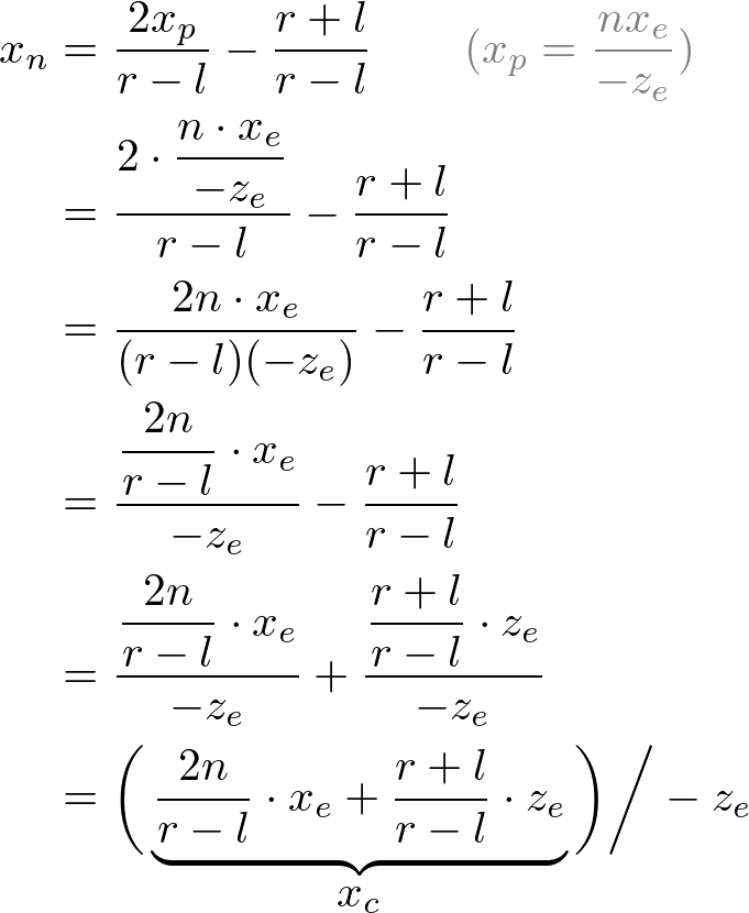
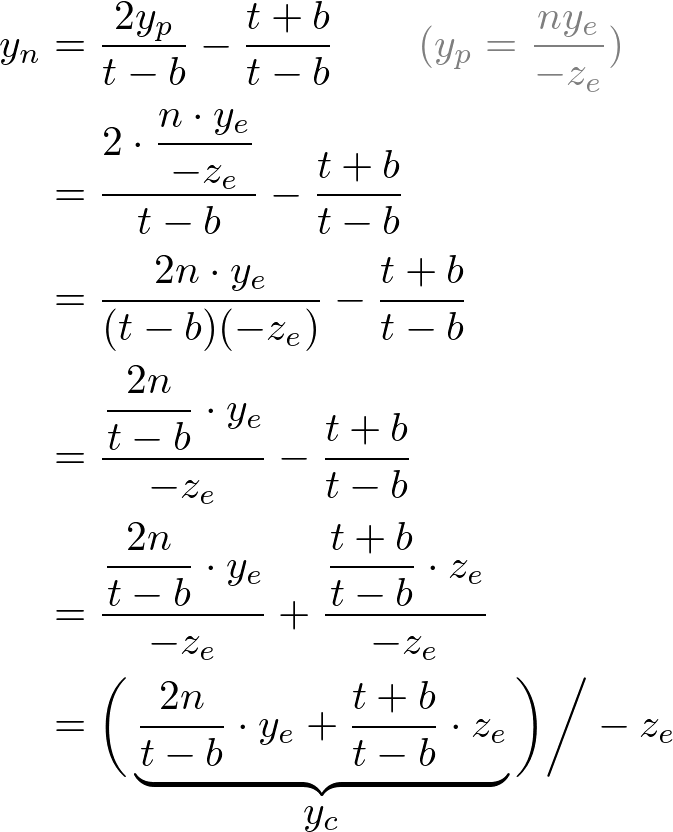
Note that we make both terms of each equation divisible by -ze for perspective division (xc/wc, yc/wc). And we set wc to -ze earlier, and the terms inside parentheses become xc and yc of the clip coordiantes.
From these equations, we can find the 1st and 2nd rows of GL_PROJECTION matrix.
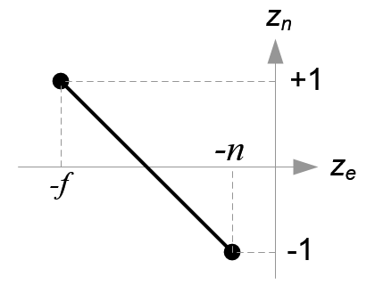
Now, we only have the 3rd row of GL_PROJECTION matrix to solve. Finding zn is a little different from others because ze in eye space is always projected to -n on the near plane. But we need unique z value for the clipping and depth test. Plus, we should be able to unproject (inverse transform) it. Since we know z does not depend on x or y value, we borrow w-component to find the relationship between zn and ze. Therefore, we can specify the 3rd row of GL_PROJECTION matrix like this.
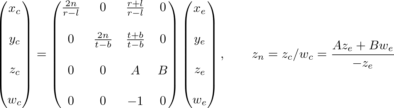
In eye space, we equals to 1. Therefore, the equation becomes;
![]()
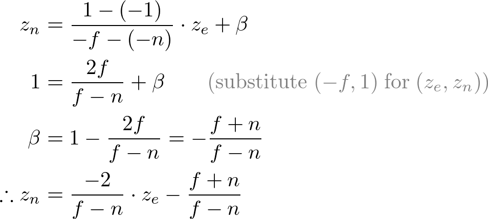
To find the coefficients, A and B, we use the (ze, zn) relation; (-n, -1) and (-f, 1), and put them into the above equation.
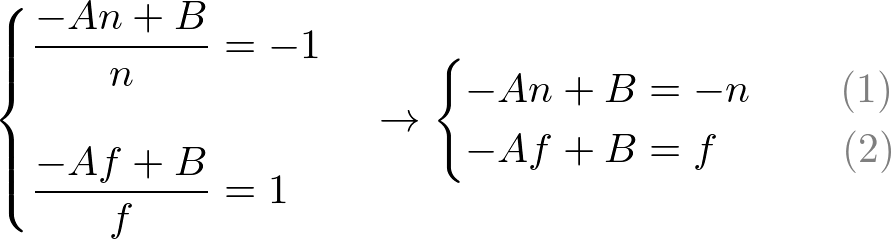
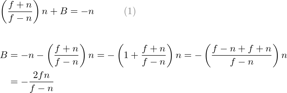
To solve the equations for A and B, rewrite eq.(1) for B;
![]()
Substitute eq.(1') to B in eq.(2), then solve for A;
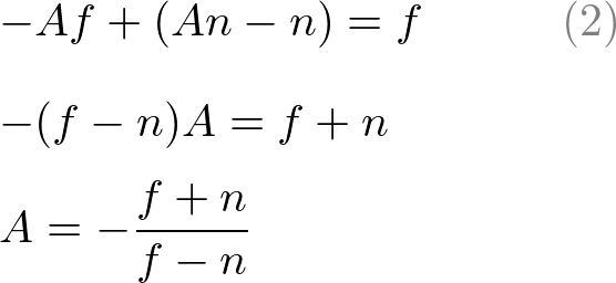
Put A into eq.(1) to find B;
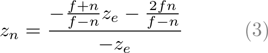
We found A and B. Therefore, the relation between ze and zn becomes;
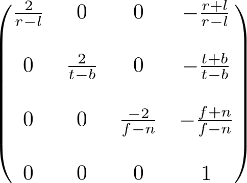
Finally, we found all entries of GL_PROJECTION matrix. The complete projection matrix is;
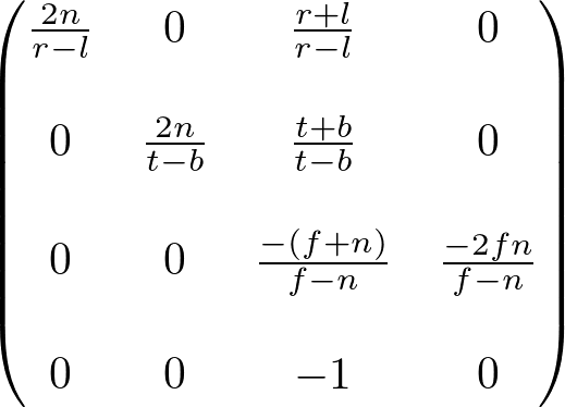
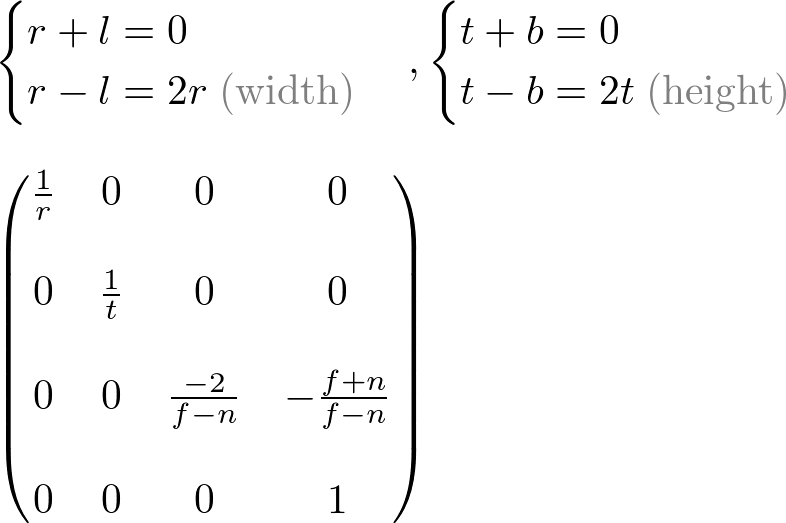
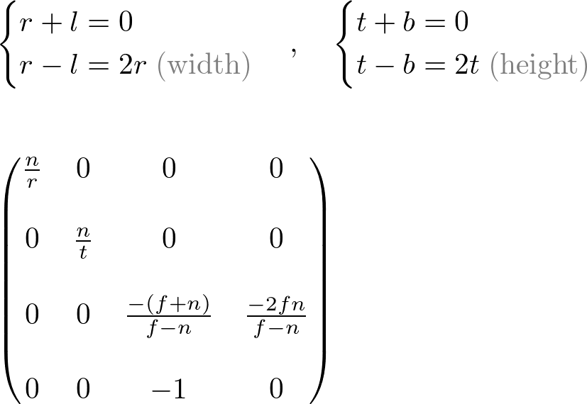
This projection matrix is for a general frustum. If the viewing volume is symmetric, which is ![]() and
and ![]() , then it can be simplified as;
, then it can be simplified as;
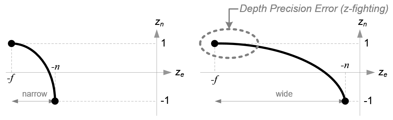
Before we move on, please take a look at the relation between ze and zn, eq.(3) once again. You notice it is a rational function and is non-linear relationship between ze and zn. It means there is very high precision at the near plane, but very little precision at the far plane. If the range [-n, -f] is getting larger, it causes a depth precision problem (z-fighting); a small change of ze around the far plane does not affect on zn value. The distance between n and f should be short as possible to minimize the depth buffer precision problem.
Infinite Perspective Matrix
The perspective projection matrix can be simplified by setting the far plane to ∞ in the third row of the perspective matrix.
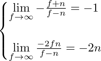
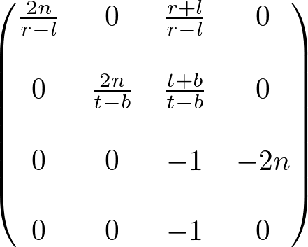
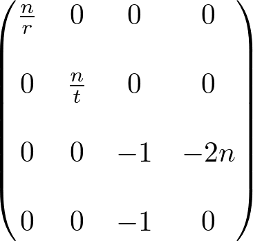
Therefore, both general and symmetric perspective projection matices with infinite far plane become;
Note that the infinite projection matrix still suffers from the depth precision error .
Perspective Matrix with Field of View (FOV)
It is hard to determine 4 parameters (left, right, top, and bottom) properly with a given near and far planes for the perspective projection on a specific window dimension. You can easily derive these 4 parameters from the vertical/horizontal field of view angle and the aspect ratio, width/height. However these conversion are limited for a symmetric perspective projection matrix.
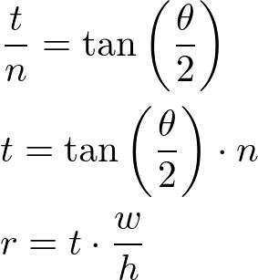
Using Vertical FOV
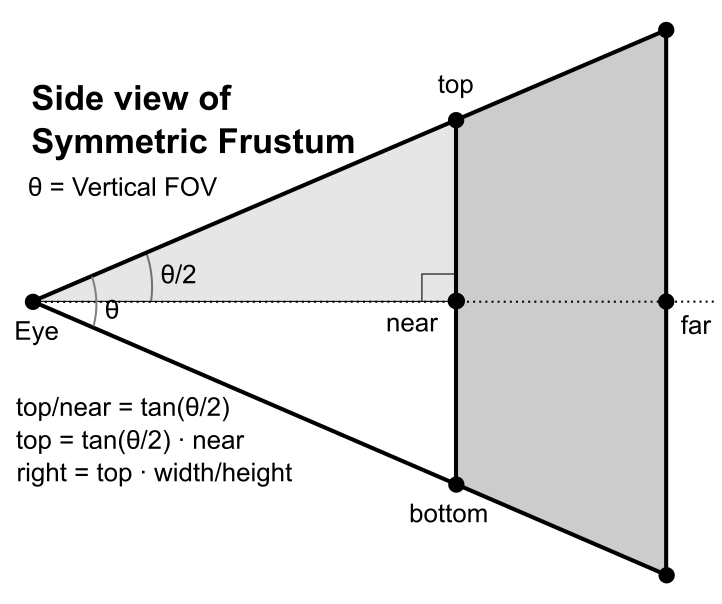
If the vertical field of view is θ and the screen width and height are known, the left, right, top, and bottom parameters can be computed by using right-angle triangle. First, find the half height (top) using tangent of half vertical FOV angle, then compute the half width (right) using the aspect ratio of the screen width and height.
// This creates a symmetric frustum with vertical FOV
// by converting 4 params (fovy, aspect=w/h, near, far)
// to 6 params (l, r, b, t, n, f)
Matrix4 makeFrustum(float fovY, float aspectRatio, float front, float back)
{
    const float DEG2RAD = acos(-1.0f) / 180;

    float tangent = tan(fovY/2 * DEG2RAD);    // tangent of half fovY
    float top = front * tangent;              // half height of near plane
    float right = top * aspectRatio;          // half width of near plane

    // params: left, right, bottom, top, near(front), far(back)
    Matrix4 matrix;
    matrix[0]  =  front / right;
    matrix[5]  =  front / top;
    matrix[10] = -(back + front) / (back - front);
    matrix[11] = -1;
    matrix[14] = -(2 * back * front) / (back - front);
    matrix[15] =  0;
    return matrix;
}
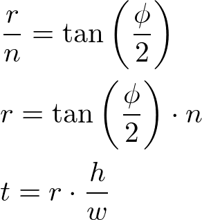
Using Horizontal FOV
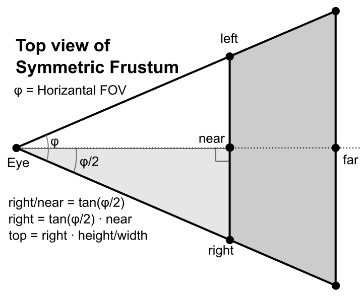
First, compute the half width (right) with tangent of the half horizontal FOV angle. Then, compute the half height (top) using the aspect ratio of the screen width and height.
// This creates a symmetric frustum with horizontal FOV
// by converting 4 params (fovx, aspect=w/h, near, far)
// to 6 params (l, r, b, t, n, f)
Matrix4 makeFrustum(float fovX, float aspectRatio, float front, float back)
{
    const float DEG2RAD = acos(-1.0f) / 180;

    float tangent = tan(fovX/2 * DEG2RAD);    // tangent of half fovX
    float right = front * tangent;            // half width of near plane
    float top = right / aspectRatio;          // half height of near plane

    // params: left, right, bottom, top, near(front), far(back)
    Matrix4 matrix;
    matrix[0]  =  front / right;
    matrix[5]  =  front / top;
    matrix[10] = -(back + front) / (back - front);
    matrix[11] = -1;
    matrix[14] = -(2 * back * front) / (back - front);
    matrix[15] =  0;
    return matrix;
}
Orthographic Projection
Constructing GL_PROJECTION matrix for orthographic projection is much simpler than perspective mode.
All xe, ye and ze components in eye space are linearly mapped to NDC. We just need to scale a rectangular volume to a cube, then move it to the origin. Let's find out the elements of GL_PROJECTION using linear relationship.
Since w-component is not necessary for orthographic projection, the 4th row of GL_PROJECTION matrix remains as (0, 0, 0, 1). Therefore, the complete GL_PROJECTION matrix for orthographic projection is;
It can be further simplified if the viewing volume is symmetrical, ![]() and
and ![]() .
.