OpenGL Cylinder, Prism & Pipe
Related Topics: OpenGL Cone & Pyramid, OpenGL Sphere, OpenGL Torus
Download: cylinder.zip, cylinderShader.zip, pipe.zip, pipeShader.zip
- Cylinder & Prism
- Example: Drawing Cylinder
- Pipe (Tube)
- Example: Extrude Pipe Along Path
- Example: WebGL Cylinder (Interactive Demo)
This page describes how to generate a cylinder geometry using C++ and how to draw it in OpenGL.
Cylinder & Prism
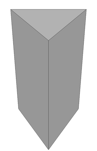
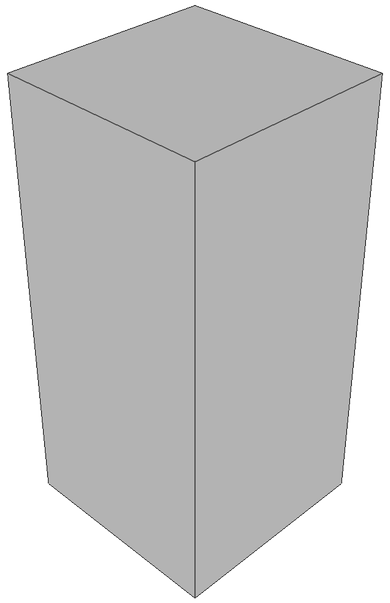
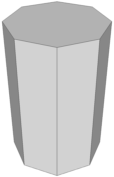
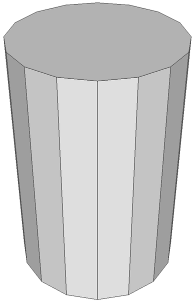
The definition of a cylinder is a 3D closed surface that has 2 parallel circular bases at the ends and connected by a curved surface (side). Similarly, a prism is a 3D closed surface that has 2 parallel polygonal bases connected by flat surfaces.
Since we cannot draw a perfect circular base and curved side of the cylinder, we only sample a limited amount of points by dividing the base by sectors (sides). Therefore, it is technically constructing a prism by connecting these sampled points together. As the number of samples increases, the geometry is closer to a cylinder.
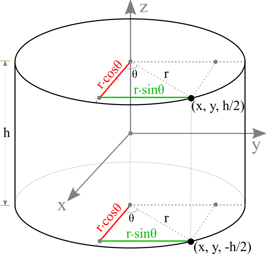
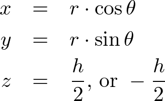
Suppose a cylinder is centered at the origin and its radius is r and the height is h. An arbitrary point (x, y, z) on the cylinder can be computed from the equation of circle with the corresponding sector angle θ.
The range of sector angles is from 0 to 360 degrees. The sector angle for each step can be calculated by the following;
![]()
The following C++ code generates all vertices of the cylinder with the given base radius, height and the number of sectors (slices). It also creates other vertex attributes; surface normals and texture coordinates.
In order to reduce multiple computations of sine and cosine, we compute the vertices of a unit circle on XY plane only once, and then re-use these points multiple times by scaling with the base radius. These are also used for the normal vectors of the side faces of the cylinder.
// generate a unit circle on XY-plane
std::vector<float> Cylinder::getUnitCircleVertices()
{
    const float PI = 3.1415926f;
    float sectorStep = 2 * PI / sectorCount;
    float sectorAngle;  // radian

    std::vector<float> unitCircleVertices;
    for(int i = 0; i <= sectorCount; ++i)
    {
        sectorAngle = i * sectorStep;
        unitCircleVertices.push_back(cos(sectorAngle)); // x
        unitCircleVertices.push_back(sin(sectorAngle)); // y
        unitCircleVertices.push_back(0);                // z
    }
    return unitCircleVertices;
}
...

// generate vertices for a cylinder
void Cylinder::buildVerticesSmooth()
{
    // clear memory of prev arrays
    std::vector<float>().swap(vertices);
    std::vector<float>().swap(normals);
    std::vector<float>().swap(texCoords);

    // get unit circle vectors on XY-plane
    std::vector<float> unitVertices = getUnitCircleVertices();

    // put side vertices to arrays
    for(int i = 0; i < 2; ++i)
    {
        float h = -height / 2.0f + i * height;           // z value; -h/2 to h/2
        float t = 1.0f - i;                              // vertical tex coord; 1 to 0

        for(int j = 0, k = 0; j <= sectorCount; ++j, k += 3)
        {
            float ux = unitVertices[k];
            float uy = unitVertices[k+1];
            float uz = unitVertices[k+2];
            // position vector
            vertices.push_back(ux * radius);             // vx
            vertices.push_back(uy * radius);             // vy
            vertices.push_back(h);                       // vz
            // normal vector
            normals.push_back(ux);                       // nx
            normals.push_back(uy);                       // ny
            normals.push_back(uz);                       // nz
            // texture coordinate
            texCoords.push_back((float)j / sectorCount); // s
            texCoords.push_back(t);                      // t
        }
    }

    // the starting index for the base/top surface
    //NOTE: it is used for generating indices later
    int baseCenterIndex = (int)vertices.size() / 3;
    int topCenterIndex = baseCenterIndex + sectorCount + 1; // include center vertex

    // put base and top vertices to arrays
    for(int i = 0; i < 2; ++i)
    {
        float h = -height / 2.0f + i * height;           // z value; -h/2 to h/2
        float nz = -1 + i * 2;                           // z value of normal; -1 to 1

        // center point
        vertices.push_back(0);     vertices.push_back(0);     vertices.push_back(h);
        normals.push_back(0);      normals.push_back(0);      normals.push_back(nz);
        texCoords.push_back(0.5f); texCoords.push_back(0.5f);

        for(int j = 0, k = 0; j < sectorCount; ++j, k += 3)
        {
            float ux = unitVertices[k];
            float uy = unitVertices[k+1];
            // position vector
            vertices.push_back(ux * radius);             // vx
            vertices.push_back(uy * radius);             // vy
            vertices.push_back(h);                       // vz
            // normal vector
            normals.push_back(0);                        // nx
            normals.push_back(0);                        // ny
            normals.push_back(nz);                       // nz
            // texture coordinate
            texCoords.push_back(-ux * 0.5f + 0.5f);      // s
            texCoords.push_back(-uy * 0.5f + 0.5f);      // t
        }
    }
}
This C++ class provides buildVerticesSmooth() and buildVerticesFlat() functions depending on surface smoothness. The constructor also takes additional parameters to construct various shapes of a cylinder, similar to OpenGL gluCylinder() function.
The parameters of the cylinder class are;
- the base radius (float)
- the top radius (float)
- the height (float)
- the number of sectors (int)
- the number of stacks (int)
- smoothness (bool)
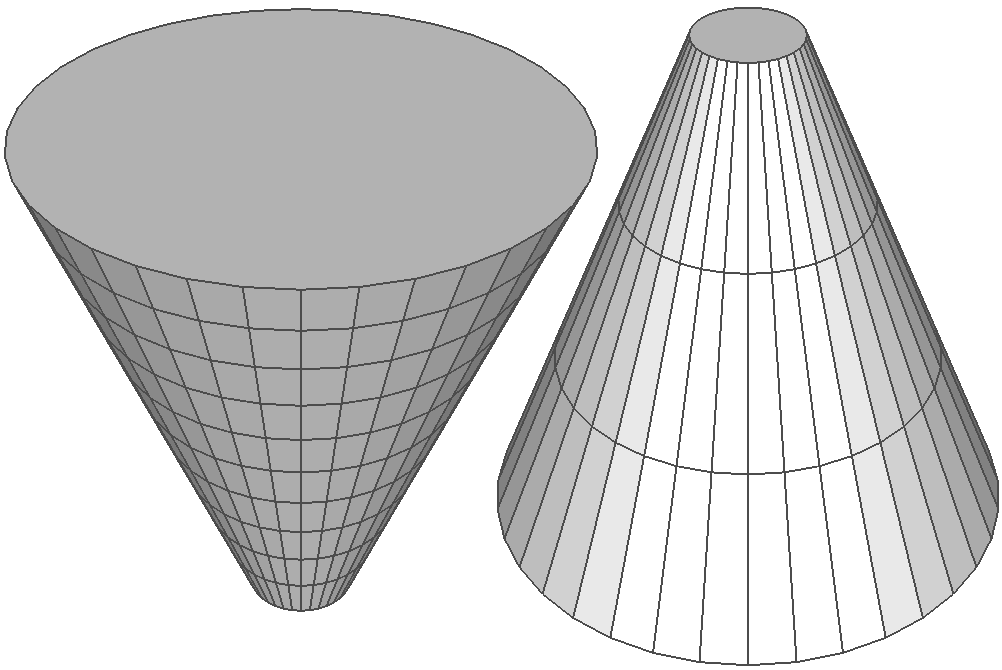
For instance, if the base radius is 0, it becomes a cone shape. For more details, please refer to Cylinder.cpp class.
In order to draw the surface of a cylinder in OpenGL, you must triangulate adjacent vertices counterclockwise to form polygons. Each sector on the side surface requires 2 triangles. The total number of triangles for the side is 2 × sectorCount. And the number of triangles for the base or top surface is the same as the number of sectors. (You may use GL_TRIANGLE_FAN for the base/top instead of GL_TRIANGLES.)
The code snippet to generate all the triangles of a cylinder may look like;
// generate CCW index list of cylinder triangles
std::vector<int> indices;
int k1 = 0;                         // 1st vertex index at base
int k2 = sectorCount + 1;           // 1st vertex index at top

// indices for the side surface
for(int i = 0; i < sectorCount; ++i, ++k1, ++k2)
{
    // 2 triangles per sector
    // k1 => k1+1 => k2
    indices.push_back(k1);
    indices.push_back(k1 + 1);
    indices.push_back(k2);

    // k2 => k1+1 => k2+1
    indices.push_back(k2);
    indices.push_back(k1 + 1);
    indices.push_back(k2 + 1);
}

// indices for the base surface
//NOTE: baseCenterIndex and topCenterIndices are pre-computed during vertex generation
//      please see the previous code snippet
for(int i = 0, k = baseCenterIndex + 1; i < sectorCount; ++i, ++k)
{
    if(i < sectorCount - 1)
    {
        indices.push_back(baseCenterIndex);
        indices.push_back(k + 1);
        indices.push_back(k);
    }
    else // last triangle
    {
        indices.push_back(baseCenterIndex);
        indices.push_back(baseCenterIndex + 1);
        indices.push_back(k);
    }
}

// indices for the top surface
for(int i = 0, k = topCenterIndex + 1; i < sectorCount; ++i, ++k)
{
    if(i < sectorCount - 1)
    {
        indices.push_back(topCenterIndex);
        indices.push_back(k);
        indices.push_back(k + 1);
    }
    else // last triangle
    {
        indices.push_back(topCenterIndex);
        indices.push_back(k);
        indices.push_back(topCenterIndex + 1);
    }
}
Example: Drawing Cylinder
Download: cylinder.zip, cylinderShader.zip (Updated: 2025-10-23)
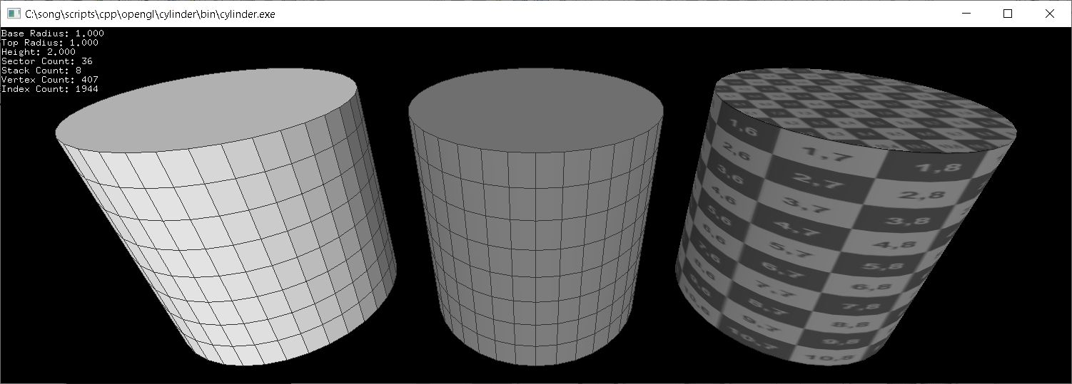
This example constructs cylinders with 36 sectors and 8 stacks, but with different shadings; flat, smooth or textured. With the default constructor (without arguments), it generates a cylinder with base/top radius = 1, height = 2, sectors = 36, and stacks = 1. By default, the top surface is facing to +Z axis, but it can be changed by the last parameter of Cylinder class constructor (X=1, Y=2 or Z=3), or by calling setUpAxis() function after it is constructed. You could also pass the custom parameters to the constructor, similar to gluCylinder(). Press the space key to change the number of sectors and stacks of the cylinders.
The minimum number of sectors and stacks are 2 and 1 respectively. If the sector count is 2, it becomes a double-sided rectangle.
Cylinder.cpp class provides pre-defined drawing functions using OpenGL VertexArray; draw(), drawWithLines(), drawLines(), drawSide(), drawBase() and drawTop().
// create a cylinder with base radius=1, top radius=2, height=3,
// height=4, sectors=5, stacks=6, smooth=true, up-axis=Z(3)
Cylinder cylinder(1, 2, 3, 4, 5, 6, true, 3);

// can change parameters later
cylinder.setBaseRadius(1.5f);
cylinder.setTopRadius(2.5f);
cylinder.setHeight(3.5f);
cylinder.setSectorCount(36);
cylinder.setStackCount(8);
cylinder.setSmooth(false);
cylinder.setUpAxis(2);     // X=1, Y=2, Z=3
...

// draw cylinder using vertexarray
cylinder.draw();            // draw surface only
cylinder.drawWithLines();   // draw surface and lines
cylinder.drawSide();        // draw side only
cylinder.drawTop();         // draw top only
cylinder.drawBase();        // draw botton only
This C++ class also provides getVertices(), getIndices(), getInterleavedVertices(), etc. in order to access the vertex data in GLSL. The following code draws a cylinder with interleaved vertex data using VBO and GLSL. Or, download cylinderShader.zip (with GLFW, 2025-10-23) for more details.
// create a cylinder with default params;
// radii=1, height=1, sectors=36, stacks=1, smooth=true, up-axis=Z(3)
Cylinder cylinder;

// create VAO to store all vertex array state to VAO
GLuint vaoId;
glGenVertexArrays(1, &vaoId);
glBindVertexArray(vaoId);

// create VBO to copy interleaved vertex data (V/N/T) to VBO
GLuint vboId;
glGenBuffers(1, &vboId);
glBindBuffer(GL_ARRAY_BUFFER, vboId);             // for vertex data
glBufferData(GL_ARRAY_BUFFER,                     // target
             cylinder.getInterleavedVertexSize(), // data size, # of bytes
             cylinder.getInterleavedVertices(),   // ptr to vertex data
             GL_STATIC_DRAW);                     // usage

// copy index data to VBO
GLuint iboId;
glGenBuffers(1, &iboId);
glBindBuffer(GL_ELEMENT_ARRAY_BUFFER, iboId);     // for index data
glBufferData(GL_ELEMENT_ARRAY_BUFFER,             // target
             cylinder.getIndexSize(),             // data size, # of bytes
             cylinder.getIndices(),               // ptr to index data
             GL_STATIC_DRAW);                     // usage

// activate vertex array attributes
glEnableVertexAttribArray(attVertex);
glEnableVertexAttribArray(attNormal);
glEnableVertexAttribArray(attTexCoord);

// set vertex array attributes with stride and offset
int stride = cylinder.getInterleavedStride();     // should be 32 bytes
glVertexAttribPointer(attVertex,   3, GL_FLOAT, false, stride, (void*)0);
glVertexAttribPointer(attNormal,   3, GL_FLOAT, false, stride, (void*)(sizeof(float)*3));
glVertexAttribPointer(attTexCoord, 2, GL_FLOAT, false, stride, (void*)(sizeof(float)*6));

// unbind VAO and VBOs
glBindVertexArray(0);
glBindBuffer(GL_ARRAY_BUFFER, 0);
glBindBuffer(GL_ELEMENT_ARRAY_BUFFER, 0);
...


// draw a cylinder with VBO
glBindVertexArray(vaoId);
glDrawElements(GL_TRIANGLES,                    // primitive type
               cylinder.getIndexCount(),        // # of indices
               GL_UNSIGNED_INT,                 // data type
               (void*)0);                       // offset to indices

// unbind VAO
glBindVertexArray(0);
Pipe (Tube)
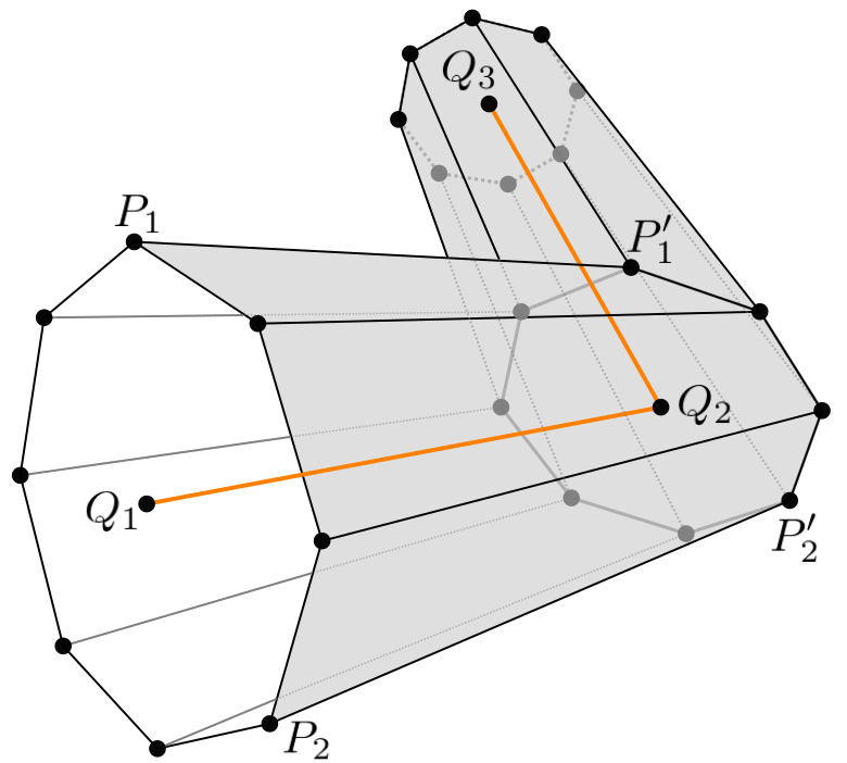
P'1 is the intersection point on a plane and a line passing P1
A common application is drawing a pipe, which is extruding a contour along a given path. Suppose the path is Q1-Q2-Q3, and a point of the contour is P1. To find the next point, P'1, we need to project P1 onto the plane at the Q2 with the normal, ![]() , where 2 path lines Q1-Q2 and Q2-Q3 are met.
, where 2 path lines Q1-Q2 and Q2-Q3 are met.
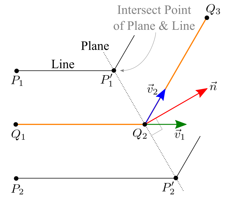
Projecting P1 to P'1 is actually finding the intersection of the point where a line and a plane are met. See the cross-section view (the right-side image above). The line equation is ![]() , which is passing P1 with the direction vector
, which is passing P1 with the direction vector ![]() .
.
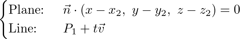
And, the plane equation can be computed by the normal vector ![]() and the point on the plane Q2 (x2, y2, z2);
and the point on the plane Q2 (x2, y2, z2);
![]()
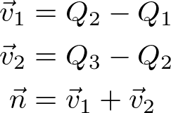
And, the normal vector is computed by adding ![]() and
and ![]() together;
together;
Finding the intersection point P'1 is solving the linear system of the plane and line;
You can find the solution of the linear system, intersection of line and plane. Or, see the detail C++ implementation in Pipe::projectContour() of Pipe.cpp and Plane.cpp.
std::vector<Vector3> Pipe::projectContour(int fromIndex, int toIndex)
{
    Vector3 v1, v2, normal, point;
    Line line;

    // find direction vectors; v1 and v2
    v1 = path[toIndex] - path[fromIndex];
    if(toIndex == (int)path.size()-1)
        v2 = v1;
    else
        v2 = path[toIndex + 1] - path[toIndex];

    // normal vector of plane at toIndex
    normal = v1 + v2;

    // define plane equation at toIndex with normal and point
    Plane plane(normal, path[toIndex]);

    // project each vertex of contour to the plane
    std::vector<Vector3>& fromContour = contours[fromIndex];
    std::vector<Vector3> toContour;
    int count = (int)fromContour.size();
    for(int i = 0; i < count; ++i)
    {
        line.set(v1, fromContour[i]);   // define line with direction and point
        point = plane.intersect(line);  // find the intersection point
        toContour.push_back(point);
    }

    // return the projected vertices of contour at toIndex
    return toContour;
}
Example: Extruding Pipe along Path
This example is drawing a pipe extruding a circular contour following a spiral path. Press D key to switch the rendering modes.
Download: pipe.zip, pipeShader.zip (Updated: 2025-10-23)
A pipe can be constructed with a pre-defined path (a sequence of points), or you can add the next point of the path if needed using Pipe::addPathPoint().
The shape of the contour is not necessarily a circle. You can provide an arbitrary shape of a contour.
To draw the surface of the pipe, use Pipe::getContour() and Pipe::getNormal() to get the vertices and normals at a given path point. Then, draw triangles between 2 contours using GL_TRIANGLE_STRIP.
If the path is a closed circle and the contour is a circle, the output geometry becomes a torus. Please see more detail about torus.
Example: WebGL Cylinder (Interactive Demo)
It is a JavaScript implementation of Cylinder class, Cylinder.js, and rendering it with WebGL. Drag the sliders to change the parameters of the cylinder. The fullscreen version is available here.
The following JavaScript code is to create and to render a cylinder object.
// create a cylinder with 6 params: baseR, topR, height, sectors, stacks, smooth
let cylinder = new Cylinder(1, 2, 3, 4, 5, false);
...

// change params of cylinder later
cylinder.setBaseRadius(1);
cylinder.setTopRadius(2);
cylinder.setHeight(3);
cylinder.setSectorCount(4);
cylinder.setStackCount(5);
cylinder.setSmooth(true);
...

// draw a cylinder with interleaved mode
gl.bindBuffer(gl.ARRAY_BUFFER, cylinder.vboVertex);
gl.vertexAttribPointer(gl.program.attPosition, 3, gl.FLOAT, false, cylinder.stride, 0);
gl.vertexAttribPointer(gl.program.attNormal,   3, gl.FLOAT, false, cylinder.stride, 12);
gl.vertexAttribPointer(gl.program.attTexCoord, 2, gl.FLOAT, false, cylinder.stride, 24);

gl.bindBuffer(gl.ELEMENT_ARRAY_BUFFER, cylinder.vboIndex);
gl.drawElements(gl.TRIANGLES, cylinder.getIndexCount(), gl.UNSIGNED_SHORT, 0);
...