OpenGL Sphere
Related Topics: OpenGL Cylinder, Prism & Pipe,
Cone & Pyramid, Torus
Download: sphere.zip, sphere_vc.zip, sphereShader.zip, icosphere.zip, icosphereShader.zip, cubesphere.zip, cubesphereShader.zip
- Sphere
- Example: Sphere
- IcoSphere
- Example: Icosphere
- CubeSphere
- Example: Cubesphere
- Example: WebGL Sphere (Interactive Demo)
- Example: WebGL Cubesphere (Interactive Demo)
This page describes how to generate various spherical geometries using C++ and how to draw them with OpenGL.
Sphere
The definition of sphere is a 3D closed surface where every point on the sphere is same distance (radius) from a given point. The equation of a sphere at the origin is
![]() .
.
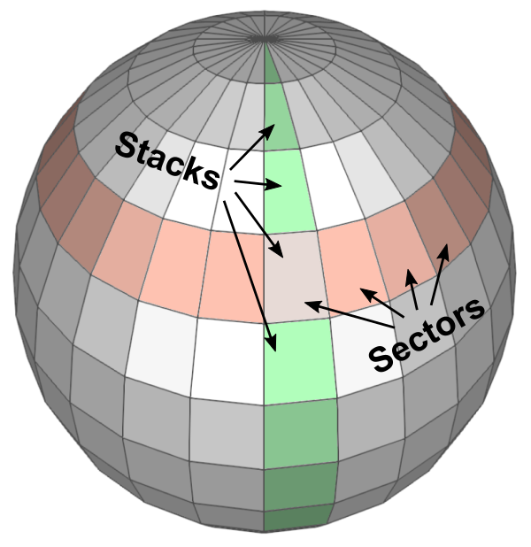
Since we cannot draw all the points on a sphere, we only sample a limited amount of points by dividing the sphere by sectors (longitude) and stacks (latitude). Then connect these sampled points together to form surfaces of the sphere.
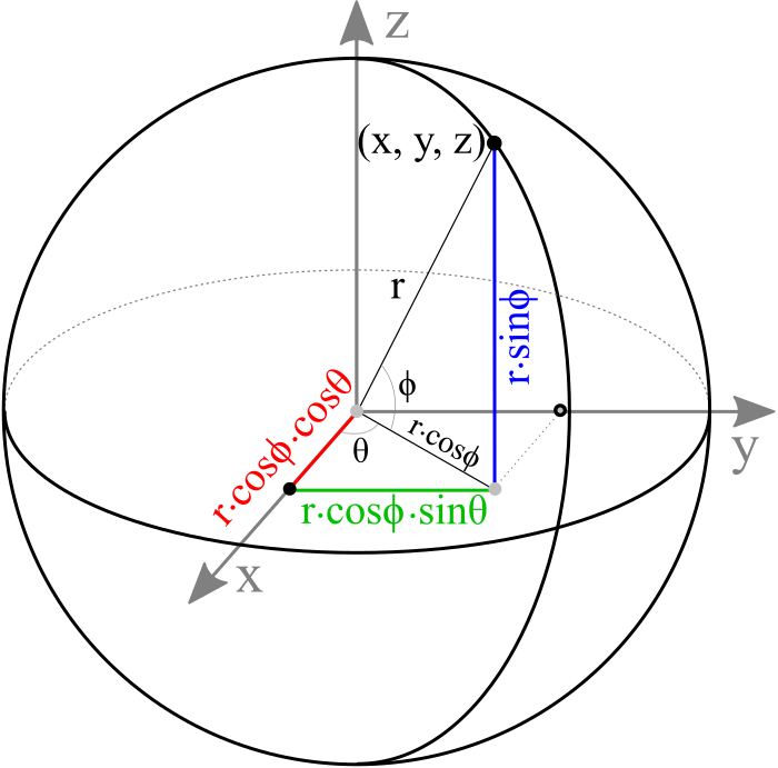
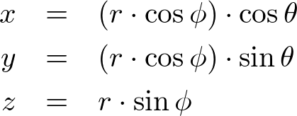
An arbitrary point (x, y, z) on a sphere can be computed by parametric equations with the corresponding sector angle θ and stack angle ϕ.
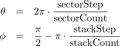
The range of sector angles is from 0 to 360 degrees, and the stack angles are from 90 (top) to -90 degrees (bottom). The sector and stack angle for each step can be calculated by the following;
The following C++ code generates all vertices of the sphere for the given radius, sectors and stacks. It also creates other vertex attributes; surface normals and texture coordinates. For more details, please refer to buildVerticesSmooth() or buildVerticesFlat() functions in Sphere.cpp class.
// clear memory of prev arrays
std::vector<float>().swap(vertices);
std::vector<float>().swap(normals);
std::vector<float>().swap(texCoords);

float x, y, z, xy;                              // vertex position
float nx, ny, nz, lengthInv = 1.0f / radius;    // vertex normal
float s, t;                                     // vertex texCoord

float sectorStep = 2 * PI / sectorCount;
float stackStep = PI / stackCount;
float sectorAngle, stackAngle;

for(int i = 0; i <= stackCount; ++i)
{
    stackAngle = PI / 2 - i * stackStep;        // starting from pi/2 to -pi/2
    xy = radius * cosf(stackAngle);             // r * cos(u)
    z = radius * sinf(stackAngle);              // r * sin(u)

    // add (sectorCount+1) vertices per stack
    // first and last vertices have same position and normal, but different tex coords
    for(int j = 0; j <= sectorCount; ++j)
    {
        sectorAngle = j * sectorStep;           // starting from 0 to 2pi

        // vertex position (x, y, z)
        x = xy * cosf(sectorAngle);             // r * cos(u) * cos(v)
        y = xy * sinf(sectorAngle);             // r * cos(u) * sin(v)
        vertices.push_back(x);
        vertices.push_back(y);
        vertices.push_back(z);

        // normalized vertex normal (nx, ny, nz)
        nx = x * lengthInv;
        ny = y * lengthInv;
        nz = z * lengthInv;
        normals.push_back(nx);
        normals.push_back(ny);
        normals.push_back(nz);

        // vertex tex coord (s, t) range between [0, 1]
        s = (float)j / sectorCount;
        t = (float)i / stackCount;
        texCoords.push_back(s);
        texCoords.push_back(t);
    }
}
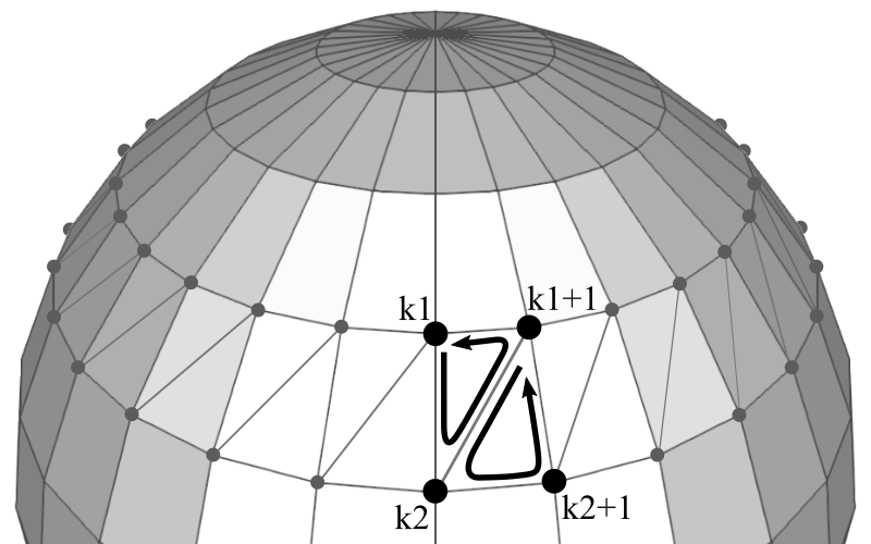
In order to draw the surface of a sphere in OpenGL, you must triangulate adjacent vertices to form polygons. It is possible to use a single triangle strip to render the whole sphere. However, if the shared vertices have different normals or texture coordinates, then a single triangle strip cannot be used.
Each sector in a stack requires 2 triangles. If the first vertex index in the current stack is k1 and the next stack is k2, then the counterclockwise orders of vertex indices of 2 triangles are;
k1 ⟶ k2 ⟶ k1+1
k1+1 ⟶ k2 ⟶ k2+1
But, the top and bottom stacks require only one triangle per sector. The code snippet to generate all triangles of a sphere may look like;
// generate CCW index list of sphere triangles
// k1--k1+1
// |  / |
// | /  |
// k2--k2+1
std::vector<int> indices;
std::vector<int> lineIndices;
int k1, k2;
for(int i = 0; i < stackCount; ++i)
{
    k1 = i * (sectorCount + 1);     // beginning of current stack
    k2 = k1 + sectorCount + 1;      // beginning of next stack

    for(int j = 0; j < sectorCount; ++j, ++k1, ++k2)
    {
        // 2 triangles per sector excluding first and last stacks
        // k1 => k2 => k1+1
        if(i != 0)
        {
            indices.push_back(k1);
            indices.push_back(k2);
            indices.push_back(k1 + 1);
        }

        // k1+1 => k2 => k2+1
        if(i != (stackCount-1))
        {
            indices.push_back(k1 + 1);
            indices.push_back(k2);
            indices.push_back(k2 + 1);
        }

        // store indices for lines
        // vertical lines for all stacks, k1 => k2
        lineIndices.push_back(k1);
        lineIndices.push_back(k2);
        if(i != 0)  // horizontal lines except 1st stack, k1 => k+1
        {
            lineIndices.push_back(k1);
            lineIndices.push_back(k1 + 1);
        }
    }
}
Example: Sphere
Download: (Updated: 2025-10-23)
- sphere.zip (with freeglut)
- sphere_vc.zip (with VisualStudio)
- sphereShader.zip (with GLFW)
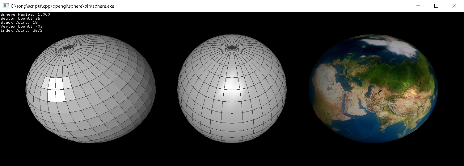
This example constructs spheres with 36 sectors and 18 stacks, but with different shadings; flat, smooth or textured. Sphere.cpp class provides pre-defined functions; draw(), drawWithLines() and drawLines(), to draw a sphere using OpenGL VertexArray.
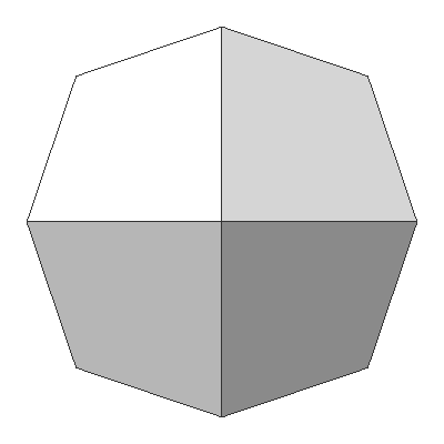
The minimum number of stacks and sectors are 2. For example, if stacks=2 and sectors=2, then it becomes a double-sided square. If stacks=2 and sectors=18, then it is a round disc with 2 sides.
By default, the north pole of the sphere is facing to +Z axis. But, it can be changed by the last parameter of Sphere class contructor (X=1, Y=2, or Z=3), or by calling setUpAxis() function after it is constructed.
// create a sphere with radius=1, sectors=36, stacks=18,
// smooth=true(default), up-axis=Z(default)
Sphere sphere(1.0f, 36, 18);
Sphere sphere(1.0f, 36, 18, true, 3);  // same as above
Sphere sphere(1.0f, 2, 18, false, 3);  // double-sided disc

// can change parameters later
sphere.setRadius(2.0f);
sphere.setSectorCount(72);
sphere.setStackCount(24);
sphere.setSmooth(false);
sphere.setUpAxis(2);                   // X=1, Y=2, Z=3
...

// draw sphere using vertexarray
sphere.draw();
This C++ class also provides getVertices(), getIndices(), getInterleavedVertices(), etc. in order to access the vertex data in GLSL. The following code draws a sphere with interleaved vertex data using VBO, VAO and GLSL. Or, download sphereShader.zip (with GLFW) for more details.
// create a sphere with default params;
// radius=1, sectors=36, stacks=18, smooth=true
Sphere sphere;

// create VAO to store all vertex array state to VAO
GLuint vaoId;
glGenVertexArrays(1, &vaoId);
glBindVertexArray(vaoId);

// create VBO to copy interleaved vertex data (V/N/T) to VBO
GLuint vboId;
glGenBuffers(1, &vboId);
glBindBuffer(GL_ARRAY_BUFFER, vboId);           // for vertex data
glBufferData(GL_ARRAY_BUFFER,                   // target
             sphere.getInterleavedVertexSize(), // data size, # of bytes
             sphere.getInterleavedVertices(),   // ptr to vertex data
             GL_STATIC_DRAW);                   // usage

// create VBO to copy index data to VBO
GLuint iboId;
glGenBuffers(1, &iboId);
glBindBuffer(GL_ELEMENT_ARRAY_BUFFER, iboId);   // for index data
glBufferData(GL_ELEMENT_ARRAY_BUFFER,           // target
             sphere.getIndexSize(),             // data size, # of bytes
             sphere.getIndices(),               // ptr to index data
             GL_STATIC_DRAW);                   // usage

// activate attrib arrays
glEnableVertexAttribArray(attribVert);
glEnableVertexAttribArray(attribNorm);
glEnableVertexAttribArray(attribTex);

// set attrib arrays with stride and offset
int stride = sphere.getInterleavedStride();     // should be 32 bytes
glVertexAttribPointer(attribVert, 3, GL_FLOAT, false, stride, (void*)0);
glVertexAttribPointer(attribNorm, 3, GL_FLOAT, false, stride, (void*)(sizeof(float)*3));
glVertexAttribPointer(attribTex,  2, GL_FLOAT, false, stride, (void*)(sizeof(float)*6));

// unbind VAO and VBOs
glBindVertexArray(0);
glBindBuffer(GL_ARRAY_BUFFER, 0);
glBindBuffer(GL_ELEMENT_ARRAY_BUFFER, 0);
...


// draw a sphere with VAO
glBindVertexArray(vaoId);
glDrawElements(GL_TRIANGLES,                    // primitive type
               sphere.getIndexCount(),          // # of indices
               GL_UNSIGNED_INT,                 // data type
               (void*)0);                       // offset to indices

// unbind VAO
glBindVertexArray(0);
Since this C++ class uses cylindrical texture mapping, there is a squeeze or texture distortion at the north and south pole area. This problem can be solved using Icosphere or Cubesphere in the following sections.
Icosphere / Geosphere
Another way to create a spherical geometry is subdividing an icosahedron multiple times. Icosahedron is a regular polyhedron with 12 vertices and 20 equilateral triangles (the first left image below). Each triangle of an icosahedron is divided into multiple equal sub-triangles per subdivision. If the subdivision frequency is 3, it becomes a soccer ball like grometry, with 20 hexgonal surfaces and 12 pentagonal surfaces by combining multiple triangles.
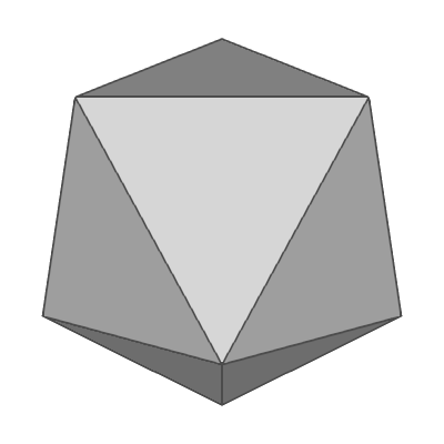
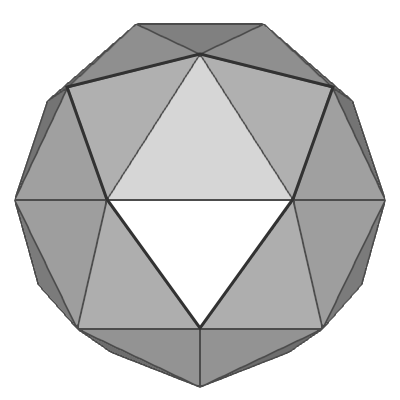
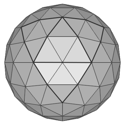
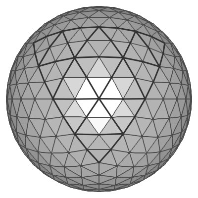
One way to construct 12 vertices of an icosahedron is using spherical coordinates; aligning 2 vertices at the north and south poles, and the other 10 vertices are placed at latitude ![]() degrees and 72° aside on the same latitude. Please see the following orthogonal projection images of icosahedron.
degrees and 72° aside on the same latitude. Please see the following orthogonal projection images of icosahedron.
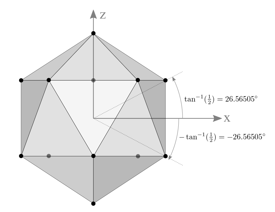
2 vertices are at north/south pole and 10 vertices are at elevation ±26.565°
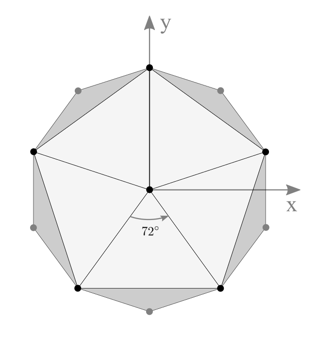
5 vertices are 72° apart at the same elevation
A typical point at latitude 26.565° and radius r can be computed by;

Note that ![]() is the elevation (height) of the point and
is the elevation (height) of the point and ![]() is the length of the projected line segment on XY plane.
is the length of the projected line segment on XY plane.
(Reference: Spherical Coordinates of Regular Icosahedron from Wikipedia)
The following C++ code is to generate 12 vertices of an icosahedron for a given radius, or you can find the complete implementation of Icosahedron.cpp or Icosphere.cpp class.
// constants
const float PI = 3.1415926f;
const float H_ANGLE = PI / 180 * 72;    // 72 degree = 360 / 5
const float V_ANGLE = atanf(1.0f / 2);  // elevation = 26.565 degree

std::vector<float> vertices(12 * 3);    // array of 12 vertices (x,y,z)
int i1, i2;                             // indices
float z, xy;                            // coords
float hAngle1 = -PI / 2 - H_ANGLE / 2;  // start from -126 deg at 1st row
float hAngle2 = -PI / 2;                // start from -90 deg at 2nd row

// the first top vertex at (0, 0, r)
vertices[0] = 0;
vertices[1] = 0;
vertices[2] = radius;

// compute 10 vertices at 1st and 2nd rows
for(int i = 1; i <= 5; ++i)
{
    i1 = i * 3;         // index for 1st row
    i2 = (i + 5) * 3;   // index for 2nd row

    z  = radius * sinf(V_ANGLE);            // elevaton
    xy = radius * cosf(V_ANGLE);            // length on XY plane

    vertices[i1] = xy * cosf(hAngle1);      // x
    vertices[i2] = xy * cosf(hAngle2);
    vertices[i1 + 1] = xy * sinf(hAngle1);  // y
    vertices[i2 + 1] = xy * sinf(hAngle2);
    vertices[i1 + 2] = z;                   // z
    vertices[i2 + 2] = -z;

    // next horizontal angles
    hAngle1 += H_ANGLE;
    hAngle2 += H_ANGLE;
}

// the last bottom vertex at (0, 0, -r)
i1 = 11 * 3;
vertices[i1] = 0;
vertices[i1 + 1] = 0;
vertices[i1 + 2] = -radius;
The subdivision algorithm is splitting the 3 edge lines of each triangle into N segments, then extruding the new point outward, so its length (the distance from the center) is the same as the sphere's radius.
std::vector<float> tmpVertices;
std::vector<float> tmpIndices;
std::vector<float> newVs((subdivision+1) * (subdivision+2) / 2 * 3);
const float *v1, *v2, *v3;          // ptr to original vertices of a triangle
float newV1[3], newV2[3], newV3[3]; // new vertex positions
unsigned int index = 0;
int i, j, k;
float a;                            // lerp alpha
unsigned int i1, i2;                // indices

// copy prev arrays
tmpVertices = vertices;
tmpIndices = indices;

// iterate each triangle of icosahedron
for(i = 0; i < tmpIndices.size(); i += 3)
{
    // get 3 vertices of a triangle of icosahedron
    v1 = &tmpVertices[tmpIndices[i] * 3];
    v2 = &tmpVertices[tmpIndices[i + 1] * 3];
    v3 = &tmpVertices[tmpIndices[i + 2] * 3];

    // add top vertex (x,y,z)
    newVs.clear();
    newVs.insert(newVs.end(), v1, v1+3);

    // find new vertices by subdividing edges
    for(j = 1; j <= subdivision; ++j)
    {
        a = (float)j / subdivision;    // lerp alpha

        // find 2 end vertices on the edges of the current row
        //          v1           //
        //         / \           // if N = 3,
        //        *---*          // lerp alpha = 1 / N
        //       / \ / \         //
        // newV1*---*---* newV2  // lerp alpha = 2 / N
        //     / \newV3/ \       //
        //    v2--*---*---v3     //
        Icosphere::interpolateVertex(v1, v2, a, radius, newV1);
        Icosphere::interpolateVertex(v1, v3, a, radius, newV2);
        for(k = 0; k <= j; ++k)
        {
            if(k == 0)      // new vertex on the left edge, newV1
                newVs.insert(newVs.end(), newV1, newV1+3);
            else if(k == j) // new vertex on the right edge, newV2
                newVs.insert(newVs.end(), newV2, newV2+3);
            else            // new vertices between newV1 and newV2
            {
                a = (float)k / j;
                Icosphere::interpolateVertex(newV1, newV2, a, radius, newV3);
                newVs.insert(newVs.end(), newV3, newV3+3);
            }
        }
    }

    // compute sub-triangles from new vertices
    for(j = 1; j <= subdivision; ++j)
    {
        for(k = 0; k < <; ++k)
        {
            // indices
            i1 = (j - 1) * j / 2 + k; // index from prev row
            i2 = j * (j + 1) / 2 + k; // index from curr row

            v1 = &newVs[i1 * 3];
            v2 = &newVs[i2 * 3];
            v3 = &newVs[(i2+1) * 3];
            addVertices(v1, v2, v3);

            // add indices
            addIndices(index, index+1, index+2);

            index += 3; // next index

            // if K is not the last, add adjacent triangle
            if(k < (j-1))
            {
                i2 = i1 + 1; // next of the prev row
                v2 = &newVs[i2 * 3];
                addVertices(v1, v3, v2);
                addIndices(index, index+1, index+2);
                index += 3;
            }
        }
    }
}
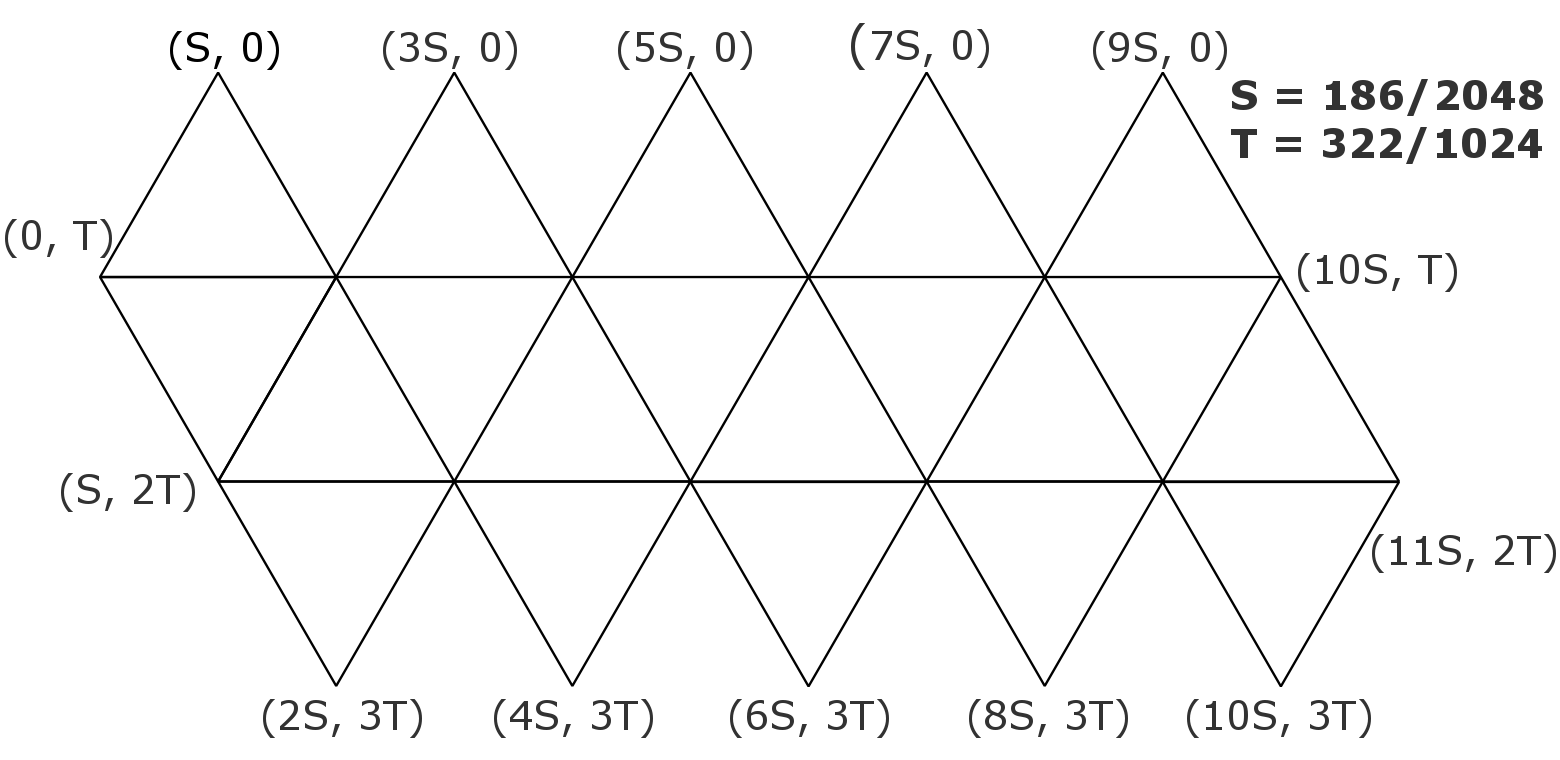
In order to generate a texture map of an icosphere, you need to unwrap the 3D geometry on a plane (paper model). I use the following texture coordinates of vertices instead of normalized coordinates from 0 to 1, so the coordinate of each vertex can be snapped to an exact pixel on the image. For example, if a texture size is 2048x1024, then the horizontal step is 186 pixels and the vertical step is 322 pixels.

Example: Icosphere
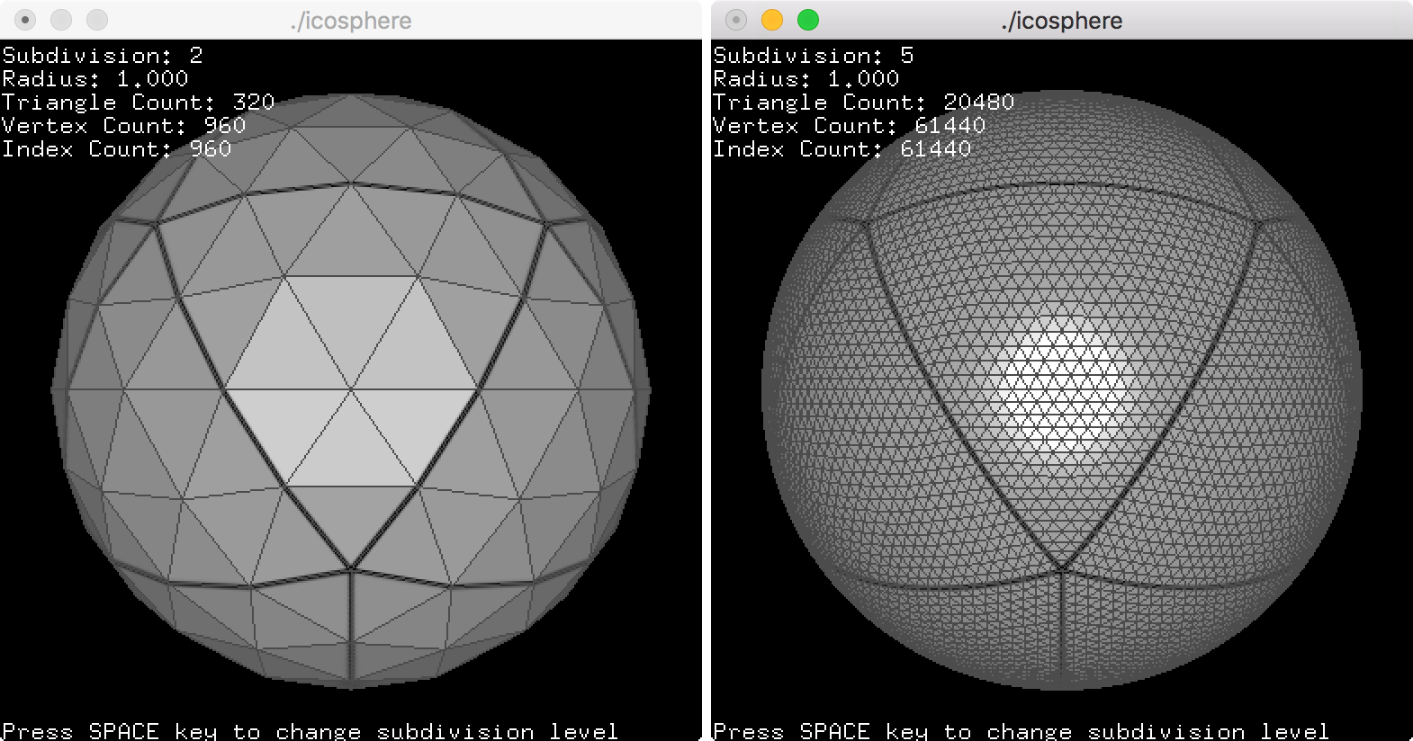
This example is to draw an icosphere with a texture. Press the spacebar key to change the subdivision level. If the subdivision frequency is 3, the icosphere consists of 180 triangles, and if the subdivision is 6, it has 720 triangles. It includes a texture template of soccer ball which consists of 20 hexagon surfaces and 12 pentagon surfaces.
- icosphere.zip (freeglut)
- icosphere_vc.zip (VisualStudio)
- icosphereShader.zip (GLFW)
- icosahedron.zip (freeglut)
Drawing an icosphere in OpenGL is identical to Sphere C++ class object. Please refer to Sphere example section above. To construct an icosphere object, it requires 3 parameters; radius, subdivision and surface smoothness. You can change the radius and subdivision level after it has been constructed. If the subdivision level is 1, then it is the same as an icosahedron.
// create icosphere with radius=1, subdivision=5 and smooth shading=true
Icosphere sphere(1.0f, 5, true);

// can change parameters later
sphere.setRadius(2.0f);
sphere.setSubdivision(6);
sphere.setSmooth(false);
...

// draw icosphere using vertexarray
sphere.draw();
...


// create VAO to store all vertex array state to VAO
GLuint vaoId;
glGenVertexArrays(1, &vaoId);
glBindVertexArray(vaoId);

// copy interleaved vertex data (V/N/T) to VBO
GLuint vboId;
glGenBuffers(1, &vboId);
glBindBuffer(GL_ARRAY_BUFFER, vboId);           // for vertex data
glBufferData(GL_ARRAY_BUFFER,                   // target
             sphere.getInterleavedVertexSize(), // data size, # of bytes
             sphere.getInterleavedVertices(),   // ptr to vertex data
             GL_STATIC_DRAW);                   // usage

// copy index data to VBO
GLuint iboId;
glGenBuffers(1, &iboId);
glBindBuffer(GL_ELEMENT_ARRAY_BUFFER, iboId);   // for index data
glBufferData(GL_ELEMENT_ARRAY_BUFFER,           // target
             sphere.getIndexSize(),             // data size, # of bytes
             sphere.getIndices(),               // ptr to index data
             GL_STATIC_DRAW);                   // usage

// activate vertex array attributes
glEnableVertexAttribArray(attribVert);
glEnableVertexAttribArray(attribNorm);
glEnableVertexAttribArray(attribTex);

// set vertex array attributes with stride and offset
int stride = sphere.getInterleavedStride();     // should be 32 bytes
glVertexAttribPointer(attribVert, 3, GL_FLOAT, false, stride, (void*)0);
glVertexAttribPointer(attribNorm, 3, GL_FLOAT, false, stride, (void*)(sizeof(float)*3));
glVertexAttribPointer(attribTex,  2, GL_FLOAT, false, stride, (void*)(sizeof(float)*6));

// unbind VAO and VBOs
glBindVertexArray(0);
glBindBuffer(GL_ARRAY_BUFFER, 0);
glBindBuffer(GL_ELEMENT_ARRAY_BUFFER, 0);
...

// draw icosphere using VAO, VBO and GLSL
glBindVertexArray(vaoId);
glDrawElements(GL_TRIANGLES,
               sphere.getIndexCount(),
               GL_UNSIGNED_INT,
               (void*)0);
...
Cubesphere
Similar to subdividing an icosahedron, a cubesphere is subdividing a cube (a regular polyhedron with 6 faces) N times to construct a spherical geometry. The characteristic of a cubesphere is that the spherical surface of the sphere is decomposed into 6 equal-area regions (+X, -X, +Y, -Y, +Z and -Z faces). It is somewhat related to the cube map, which is a method of environment mapping in computer graphics.
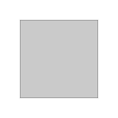
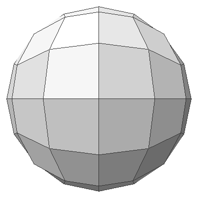
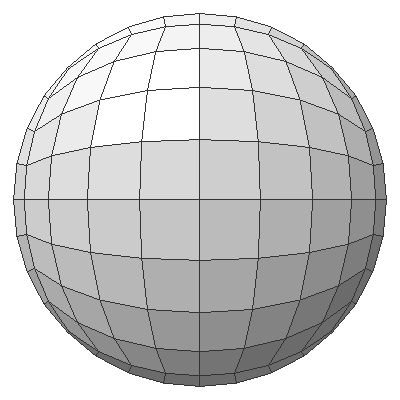
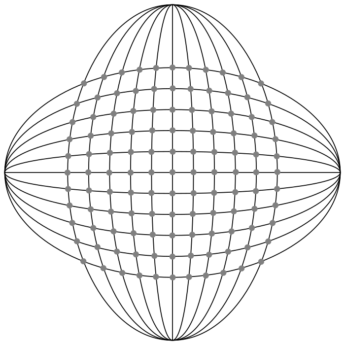
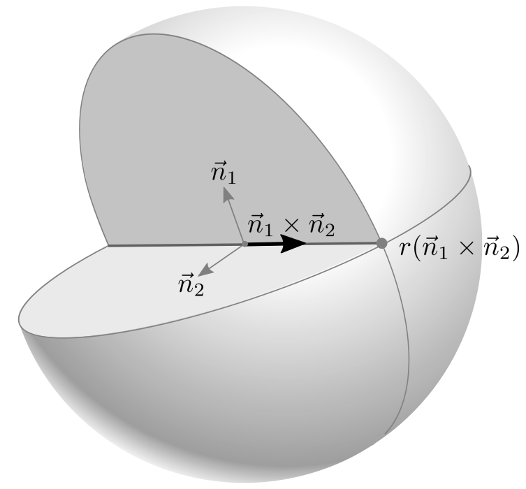
The following images represent how to construct one of the 6 regions of a cubesphere by intersecting angularly equal-distant longitudinal and latitudinal lines from -45 degree to +45 degree. A vertex on a cubesphere can be computed by the intersection of 2 plane equations. If the normal vector of the latitudinal plane is ![]() and the normal of the longitudinal plane is
and the normal of the longitudinal plane is ![]() , then the direction vector of the intersect line is
, then the direction vector of the intersect line is ![]() . Finally, the vertex on the cubesphere is scaling the normalized direction vector by the radius of the sphere,
. Finally, the vertex on the cubesphere is scaling the normalized direction vector by the radius of the sphere, ![]() .
.

The following C++ code is generating a face of a unit cubesphere, which is facing +X axis and the radius is 1.
// generate vertices for +X face only by intersecting 2 circular planes
// (longitudinal and latitudinal) at the given longitude/latitude angles
std::vector<float> buildUnitPositiveX(int pointsPerRow)
{
    const float DEG2RAD = acos(-1) / 180.0f;

    std::vector<float> vertices;
    float n1[3];        // normal of longitudinal plane rotating along Y-axis
    float n2[3];        // normal of latitudinal plane rotating along Z-axis
    float v[3];         // direction vector intersecting 2 planes, n1 x n2
    float a1;           // longitudinal angle along Y-axis
    float a2;           // latitudinal angle along Z-axis

    // rotate latitudinal plane from 45 to -45 degrees along Z-axis (top-to-bottom)
    for(unsigned int i = 0; i < pointsPerRow; ++i)
    {
        // normal for latitudinal plane
        // if latitude angle is 0, then normal vector of latitude plane is n2=(0,1,0)
        // therefore, it is rotating (0,1,0) vector by latitude angle a2
        a2 = DEG2RAD * (45.0f - 90.0f * i / (pointsPerRow - 1));
        n2[0] = -sin(a2);
        n2[1] = cos(a2);
        n2[2] = 0;

        // rotate longitudinal plane from -45 to 45 along Y-axis (left-to-right)
        for(unsigned int j = 0; j < pointsPerRow; ++j)
        {
            // normal for longitudinal plane
            // if longitude angle is 0, then normal vector of longitude is n1=(0,0,-1)
            // therefore, it is rotating (0,0,-1) vector by longitude angle a1
            a1 = DEG2RAD * (-45.0f + 90.0f * j / (pointsPerRow - 1));
            n1[0] = -sin(a1);
            n1[1] = 0;
            n1[2] = -cos(a1);

            // find direction vector of intersected line, n1 x n2
            v[0] = n1[1] * n2[2] - n1[2] * n2[1];
            v[1] = n1[2] * n2[0] - n1[0] * n2[2];
            v[2] = n1[0] * n2[1] - n1[1] * n2[0];

            // normalize direction vector
            float scale = 1 / sqrt(v[0]*v[0] + v[1]*v[1] + v[2]*v[2]);
            v[0] *= scale;
            v[1] *= scale;
            v[2] *= scale;

            // add a vertex into array
            vertices.push_back(v[0]);
            vertices.push_back(v[1]);
            vertices.push_back(v[2]);
        }
    }

    return vertices;
}
The other 5 faces can be generated by repeating the above procedure, or swapping and/or negating axis of the vertices of +X face to optimize redundant sine/cosine computations. For example, the vertices of -X face are only negating x and z coordinates of +X face, and +Y face requires swapping x → y, y → -z, and z → -x.
+X Face: ( x,  y,  z)

-X Face: (-x,  y, -z)
+Y Face: (-z,  x, -y)
-Y Face: (-z, -x,  y)
+Z Face: (-z,  y,  x)
-Z Face: ( z,  y, -x)
Please see the detail implementation in buildVerticesFlat() and buildVerticesSmooth() of C++ Cubesphere class to construct all 6 faces.
Example: Cubesphere
Download: (Updated: 2025-10-23)
- cubesphere.zip (freeglut)
- cubesphere_vc.zip (VisualStudio)
- cubesphereShader.zip (GLFW)
- cubesphereEarth.zip (freeglut)
- cubesphereEarthShader.zip (GLFW)
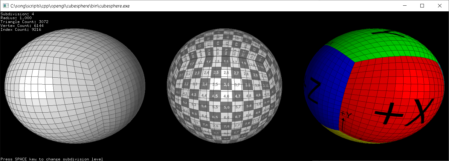
This example is to draw cubespheres with various shadings; the left sphere is without texture, the center sphere is applying a 2D texture to all the 6 faces, and the right sphere is with a cube map texture (GL_ARB_texture_cube_map extension required). Press the space key to change the subdivision levels.

To construct a cubesphere object, it requires 3 parameters; radius, subdivision and surface smoothness. You can change the radius and subdivision level after it has been constructed. If the subdivision is 1, then the shape is a cube.
// create cubesphere with default constructor
// radius=1, subdivision=3 and smooth shading=true
Cubesphere sphere;
Cubesphere sphere(1, 3, true); // same as above

// can change parameters later
sphere.setRadius(2.0f);
sphere.setSubdivision(6);
sphere.setSmooth(false);
...

// draw cubesphere using vertexarray
sphere.draw();          // draw surface only
sphere.drawWithLines(); // draw surface and lines
sphere.drawFace(0);     // draw only +X face, face index:0~5
...
This C++ class provides an additional function, drawFace() to draw only the selected face for the given face index. The valid face index is 0 to 5; +X, -X, +Y, -Y, +Z, -Z face respectively.
Example: WebGL Sphere (Interactive Demo)
It is a JavaScript version of Sphere class, Sphere.js in GitHub repository, and rendering it with WebGL. Drag the sliders to change the parameters of the sphere. The fullscreen version is available at Sphere Demo.
The following JavaScript code is to create and to render a sphere object.
// create a sphere with 4 params: radius, sectors, stacks, smooth
let sphere = new Sphere(gl, 1, 36, 18, false);
...

// change params of sphere later
sphere.setRadius(2);
sphere.setSectorCount(8);
sphere.setStackCount(4);
sphere.setSmooth(true);
...

// draw a sphere with interleaved mode
gl.bindBuffer(gl.ARRAY_BUFFER, sphere.vboVertex);
gl.vertexAttribPointer(gl.program.attribPos,  3, gl.FLOAT, false, sphere.stride, 0);
gl.vertexAttribPointer(gl.program.attribNorm, 3, gl.FLOAT, false, sphere.stride, 12);
gl.vertexAttribPointer(gl.program.attribTex0, 2, gl.FLOAT, false, sphere.stride, 24);

gl.bindBuffer(gl.ELEMENT_ARRAY_BUFFER, sphere.vboIndex);
gl.drawElements(gl.TRIANGLES, sphere.getIndexCount(), gl.UNSIGNED_SHORT, 0);
...
Example: WebGL Cubesphere (Interactive Demo)
It is a JavaScript version of Cubesphere class for WebGL, Cubesphere.js. Drag the sliders to change the radius and subdivision parameters of the cubesphere. The maximum subdivision value is limited to 52 because the data type of the index array is 16-bit integer (Uint16Array), and it holds upto 65535. The fullscreen version is also available at Cubesphere Demo.
The following JavaScript code is to create and to render a cubesphere object.
// create a cubesphere with 3 params: radius, subdivision, smooth
let sphere = new Cubesphere(gl, 1, 3, true);    // default cubesphere
...

// change params of cubesphere later
sphere.setRadius(2);
sphere.setSideLength(1);
sphere.setSubdivision(5);
sphere.setSmooth(false);
...

// draw a cubesphere with interleaved mode
gl.bindBuffer(gl.ARRAY_BUFFER, sphere.vboVertex);
gl.vertexAttribPointer(gl.program.attribPos,  3, gl.FLOAT, false, sphere.stride, 0);
gl.vertexAttribPointer(gl.program.attribNorm, 3, gl.FLOAT, false, sphere.stride, 12);
gl.vertexAttribPointer(gl.program.attribTex0, 2, gl.FLOAT, false, sphere.stride, 24);

gl.bindBuffer(gl.ELEMENT_ARRAY_BUFFER, sphere.vboIndex);
gl.drawElements(gl.TRIANGLES, sphere.getIndexCount(), gl.UNSIGNED_SHORT, 0);
...